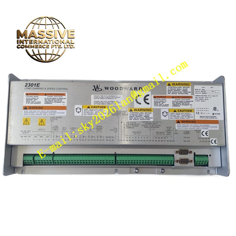
Description
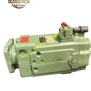
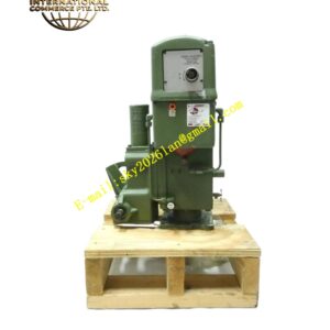
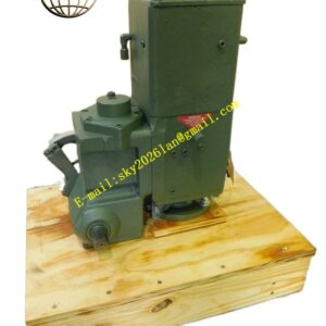
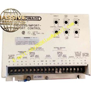
Woodward 2301E 8273-1011
Technical Specifications Digital microprocessor architecture; dual magnetic pickup speed inputs; pulse width modulated actuator drive output; digital load sharing communication; nonvolatile memory for parameter retention; 24V DC control power supply; front panel display and keypad.
Functional Features Regulates engine or turbine rotational speed to the configured setpoint. Distributes real and reactive load evenly across parallel generator units. Executes controlled speed profiles during startup and shutdown. Stores all tuning parameters in nonvolatile memory and retains settings through power loss. Provides fault alarms for speed sensor failure, actuator feedback error and internal hardware faults.
Application Scenarios Land based diesel generators, gas turbine generator packages, marine generator systems and multi-unit standby power plants.
Performance Parameters Digital high resolution speed sampling; fast dynamic response to load transients; precise load sharing between paralleled engines; stable operation across wide ambient temperature ranges.
Material Composition Enclosure is die cast aluminum alloy with protective paint; main circuit board is industrial FR‑4 multilayer PCB; keypad overlay is durable polyester membrane; terminal connectors are nickel plated copper alloy; internal memory and processor components are industrial grade.
Structural Characteristics Panel mount rectangular enclosure; front panel with LCD display, navigation keys and status LEDs; rear terminal blocks for speed sensors, actuator drive, power supply and load sharing communication wiring.
Working Principle Magnetic pickup sensors generate frequency signals proportional to prime mover shaft speed. The digital processor samples the frequency and calculates speed error relative to the reference setpoint. Control algorithms compute the required actuator drive signal to adjust fuel flow. When generators operate in parallel, controllers exchange load data via dedicated load sharing links to equalize power output.
Installation Requirements Install in a cabinet protected from direct moisture and heavy vibration. Use shielded twisted pair wire for magnetic pickup sensors. Complete engine startup test, speed tuning and parallel load testing after wiring. Save parameter files for backup after successful commissioning.
Precautions for Use Shielded sensor cables must be separated from high current power cables. Do not rely solely on this governor for overspeed protection; maintain independent mechanical overspeed trip devices. Do not open the enclosure or modify internal circuitry.