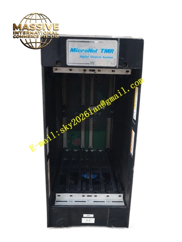
Description
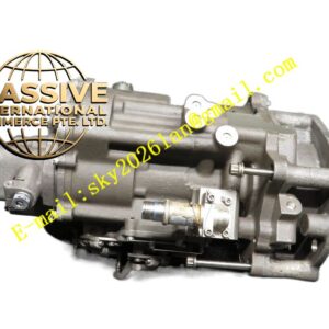
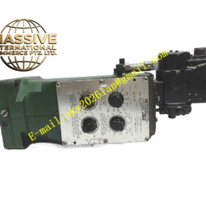
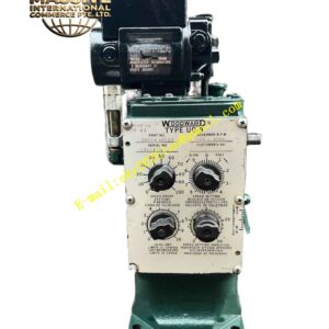
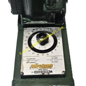
WOODWARD 5453‑277 REV B
Technical Specifications System architecture: Triple Modular Redundancy (TMR 2oo3 voting system) Supported power supply input: 88‑300 VDC, 70‑265 VAC 48‑62 Hz Built‑in redundant cooling fan assemblies Mechanical form factor: Standard cabinet rack‑mount chassis Hardware revision: REV‑B Operating temperature range: ‑40 °C ~ +85 °C Internal backplane: Multi‑layer high‑reliability backplane providing inter‑module signal routing Module slot quantity: Multiple slots for TMR CPU, I/O and hot‑swap power supply units Protection class for cabinet installation: IP20
Functional Features Provides mechanical mounting and high‑speed signal interconnection for MicroNet TMR series controller modules via internal backplane. Supports hot‑swappable redundant power supply modules for non‑stop system operation during power unit replacement. Equipped with redundant cooling fan groups for forced air cooling across all inserted modules. Distributes system reference power to all plug‑in modules. Integrates hardware fault monitoring circuits for power supply health and fan status. Supports triple‑channel signal voting logic between three redundant controller channels. Front‑panel LED status indicators display power health, fan operation and channel fault alarms.
Application Scenarios Gas turbine and steam turbine control in power generation plants. Oil‑gas industry compressor control and surge protection systems. Reciprocating gas engine generator set control. Off‑shore and marine propulsion engine safety control. Combined‑cycle power plant safety interlock systems. Critical process machinery where single‑point‑failure‑tolerant operation is mandatory.
Performance Parameters Maintains continuous system operation after single‑channel hardware fault via TMR 2‑out‑of‑3 voting mechanism. Supports hot‑swap replacement of power supply modules without system shutdown. Built‑in fan‑fail alarm signal output. Backplane signal path designed for high noise immunity in heavy industrial electromagnetic environments.
Material Composition Heavy‑duty galvanized steel chassis frame, anti‑corrosion powder‑coated metal housing, high‑reliability multi‑layer FR‑4 backplane circuit board, reinforced plastic fan frame, gold‑plated high‑current backplane connectors for module insertion.
Structural Features Rack‑mount metal cabinet chassis structure. Rear‑mounted redundant cooling fan bank. Multiple horizontal module slots for plug‑in controller, I/O and power modules. Internal passive backplane without active electronic components. Front‑accessible module extraction handles for module replacement. External wiring terminal area isolated from module insertion zone.
Working Principle All inserted TMR controller modules communicate through the internal chassis backplane. Three independent control channels execute identical control logic simultaneously. Backplane hardware enables 2‑out‑of‑3 signal voting, so output decisions follow majority channel result; single‑channel hardware fault cannot cause wrong output action. Redundant power supply modules feed shared system power bus inside chassis. Redundant fans maintain forced convection cooling for all electronic assemblies.
Installation Requirements Install chassis inside well‑ventilated industrial control cabinet with sufficient front‑to‑back airflow path. Maintain clearance for air intake and exhaust openings of cooling fans. Secure chassis firmly to cabinet mounting rails with specified fasteners. Complete all protective earth ground connections to chassis ground studs. Follow Woodward official wiring diagrams for AC/DC power input cabling. Allow adequate front‑side space for module insertion, extraction and maintenance operations.
Usage Notes Only use genuine Woodward compatible MicroNet TMR series modules inside this REV‑B chassis. Do not mix hardware revision levels of backplane and functional modules. Verify proper torque for all power‑input terminal connections. Periodically inspect cooling fan function and clean dust accumulation on fan filters. Do not insert or remove modules while chassis is powered unless module explicitly supports hot‑swap capability. Conduct full system diagnostic check after any module replacement work. Keep chassis away from locations with liquid ingress, corrosive vapor or excessive mechanical shock exposure.