Description
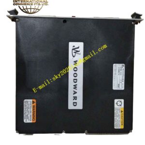
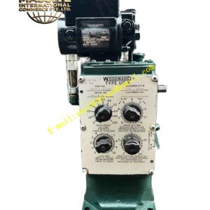
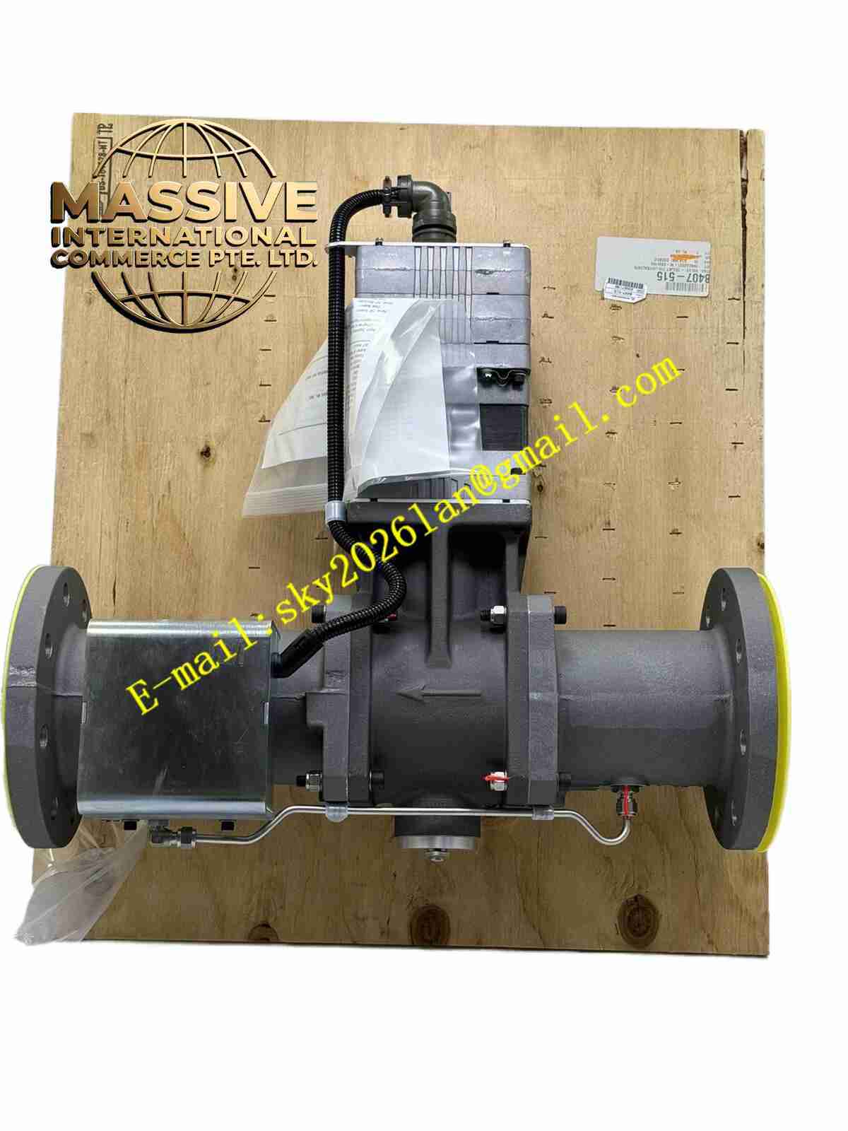
Woodward 8440-1019
Technical Specifications
- Microprocessor: 32-bit industrial-grade RISC architecture.
- Analog Inputs: 8 channels, configurable for voltage, current, or RTD.
- Digital Inputs: 12 isolated inputs for start/stop, alarms, and permissives.
- Analog Outputs: 4 isolated channels for actuator drive and gauge outputs.
- Bus Interface: Internal backplane communication for system expansion.
Functional Features
- Isochronous Load Sharing: Enables precise kW load division among parallel generators without droop.
- Programmable Logic: Includes ladder logic or function block capabilities for auxiliary control.
- Curve Generation: Supports multi-point fuel/air mapping for optimal combustion efficiency.
- Watchdog Timer: Hardware-based protection to reset the processor in case of software lockup.
Application Scenarios
Integrated into control panels for diesel generators, gas compressors, and marine propulsion engines.
Performance Parameters
- Speed Regulation: Steady-state accuracy of ±0.25% or better.
- Transient Recovery: Returns to setpoint within 3 seconds following a 50% load step.
- Update Rate: 10 ms scan time for critical control loops.
Material Composition
Multi-layer FR4 printed circuit board with immersion gold surface finish. Components are automotive or industrial-grade, rated for extended temperature ranges.
Structural Characteristics
- Edge Connector: Gold-plated fingers for reliable backplane mating.
- Mounting Holes: Standardized spacing for secure panel mounting.
- Test Points: Clearly labeled analog and digital test points for field troubleshooting.
Working Principle
The board samples all analog and digital inputs at high speed, validates signal integrity, and executes the governing algorithm. It calculates the required fuel position and outputs a pulse-width modulated (PWM) or analog signal to the actuator driver stage.
Installation Requirements
- Must be seated fully into the backplane connector before applying power.
- Ensure adequate airflow across the board to dissipate heat from power components.
- Install in a grounded, shielded enclosure to protect against EMI.
Usage Precautions
- Always use an anti-static wrist strap when handling the bare board.
- Do not attempt to repair individual components; replace the entire board assembly.
- Verify jumper and DIP switch settings match the application schematic before energizing.