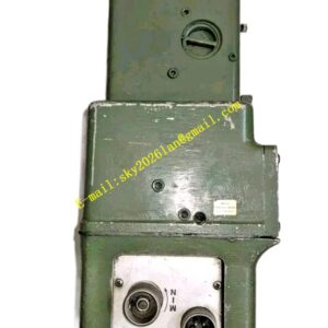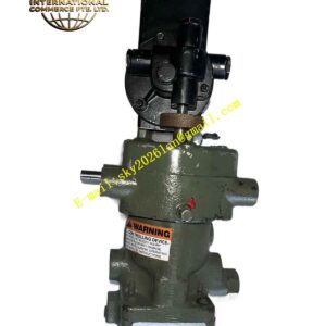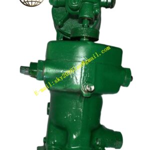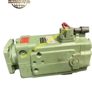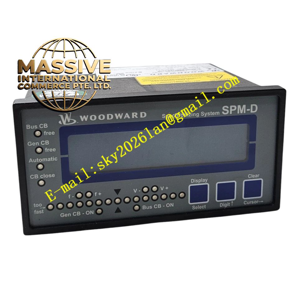
Description
Woodward 8440-1706E
Technical Specifications
- Control Modes: Supports Isochronous Load Sharing, Speed Control with Droop, and standalone Speed Control.
- Speed Input: Accepts signals from Magnetic Pickups (MPU), eddy current probes, or proximity probes.
- Control Output: 4-20 mA signal designed to drive proportional actuators or electric fuel valves.
- Power Supply: Robust 18-32 VDC isolated input.
- Processing Speed: High-speed microprocessor with millisecond-level adjustment cycles.
Functional Features
- Advanced PID Control: Features self-tuning PID algorithms with a control accuracy of ±0.1% of rated speed.
- Multi-Mode Switching: Allows seamless transitions between speed control, power control, and process parameter control modes.
- Process Parameter Control: Supports closed-loop control for auxiliary parameters like pressure, temperature, and flow.
- Safety Interlocking: Built-in logic for overspeed protection, load limiting, and fault shutdowns to ensure equipment safety.
Application Scenarios
Ideal for standby power generator sets, mechanical drive systems for compressors and pumps, and small to medium power generation units requiring dedicated, high-speed stability and simple configuration.
Performance Parameters
- Speed Range: Fully programmable to accommodate a wide variety of engine and turbine speeds.
- Response Time: Millisecond-level control loop execution for rapid transient recovery.
- Environmental Tolerance: Operating temperature range from -40°C to +85°C (-40°F to +185°F).
Material Composition
Constructed with a durable panel-mount enclosure. The internal electronics utilize high-reliability industrial components designed to withstand severe mechanical vibration and electrical noise typical in prime mover environments.
Structural Characteristics
- Form Factor: Compact module designed for standard panel cutouts or DIN rail mounting.
- Interface: Front-panel buttons and display for local configuration, tuning, and diagnostics without requiring a PC.
- Certifications: Designed to meet rigorous industrial and marine standards.
Working Principle
The 8440-1706E receives a real-time speed signal from the engine’s flywheel or turbine shaft. It compares this actual speed against the programmed setpoint and utilizes advanced PID algorithms to calculate the necessary corrective action. It then outputs a proportional 4-20 mA signal to the fuel actuator, continuously adjusting fuel flow to maintain the target speed or load.
Installation Requirements
- MPU sensors must be installed with the correct air gap and shielded cabling to prevent signal noise.
- Ensure the 18-32 VDC power supply is clean and properly fused.
- Actuator wiring must be verified for correct polarity and full stroke calibration.
Usage Precautions
- Always perform a complete actuator calibration and PID tuning after initial installation.
- Do not bypass overspeed protection circuits under any operational circumstances.
- Regularly verify the integrity of the MPU signal and actuator feedback during routine maintenance.