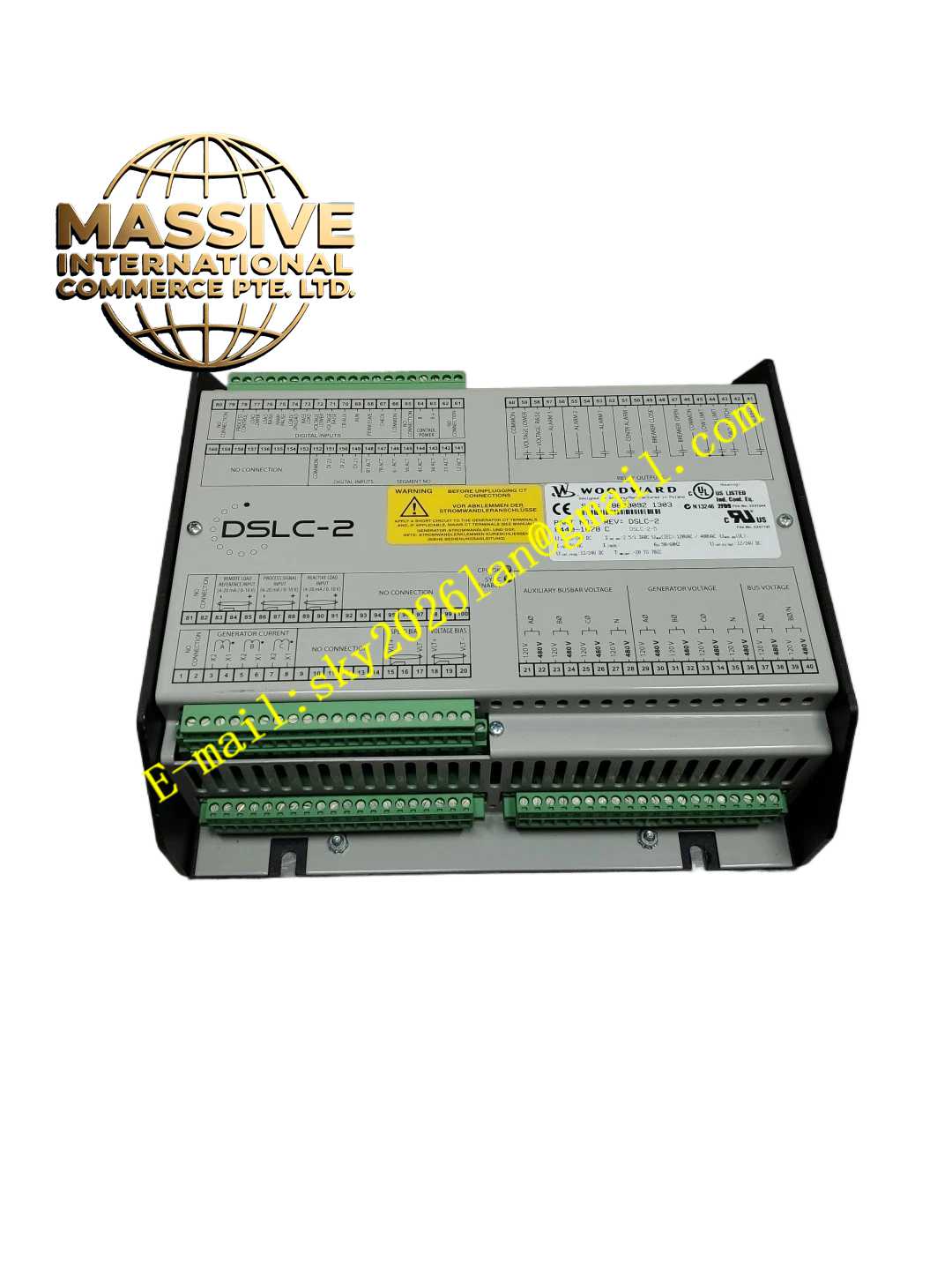
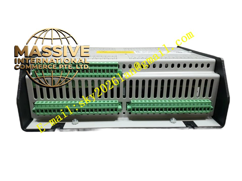
Description
Woodward 8440-1878
Technical Specifications
- Product Type: Power Supply Unit / Control Module.
- Input Voltage: Wide-range AC or DC input (e.g., 85-264 VAC or 100-300 VDC).
- Output Voltage: Regulated 24 VDC, 12 VDC, and 5 VDC rails.
- Protection: Integrated over-voltage, over-current, and short-circuit protection.
Functional Features
- Stable Power Delivery: Provides clean, ripple-free DC power to prevent noise in analog control circuits.
- Redundancy Capable: Designed to operate in parallel with identical units for N+1 power redundancy.
- Status Monitoring: Features a “Power Good” relay output and front-panel LED to indicate healthy operation.
- High Efficiency: Switching power topology minimizes heat generation and energy waste.
Application Scenarios
Integral component in MicroNet, 505E, and 2301 control panels, ensuring uninterrupted power to all electronic modules.
Performance Parameters
- Load Regulation: Excellent voltage stability (<0.5%) from no-load to full-load.
- Hold-Up Time: Sufficient energy storage to ride through brief power interruptions.
Material Composition
Industrial-grade capacitors, transformers, and switching components. Metal enclosure acting as a heat sink. Conformal-coated PCB for environmental protection.
Structural Characteristics
Plug-in module for the control rack or standalone DIN-rail mount. Front panel features voltage test points, status LEDs, and adjustment potentiometers (if applicable).
Working Principle
Rectifies and filters the incoming AC/DC power, then uses high-frequency switching to step down the voltage. A feedback loop continuously adjusts the switching duty cycle to maintain a constant output voltage despite input fluctuations or load changes.
Installation Requirements
Ensure adequate airflow across the module for cooling. Connect input power through a properly rated circuit breaker. Verify output voltage before connecting load modules.
Usage Precautions
- Never hot-swap the module unless the system explicitly supports it.
- Check input fuses if the unit fails to power up.
- Replace immediately if the “Power Good” signal is lost or output voltage drifts out of specification.