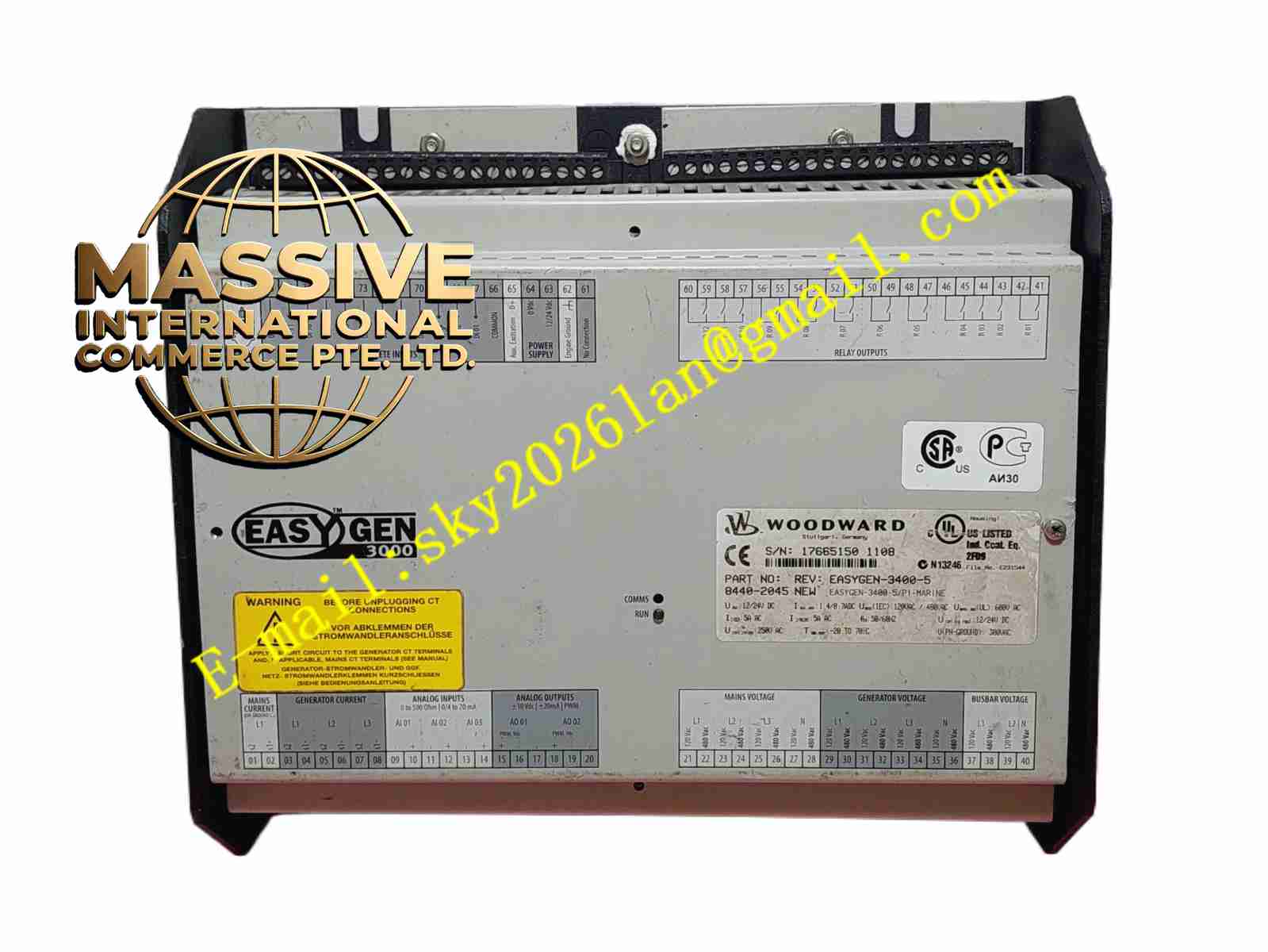
Description
Woodward 8440-2045
Technical Specifications
- Product Type: Industrial Control Module / Signal Conditioning Card.
- Signal Compatibility: Accepts standard industrial signals (4-20 mA, 0-10 VDC, RTD, Thermocouple, Dry Contacts).
- Isolation: High-voltage galvanic isolation between input channels and the system backplane.
- Update Rate: Synchronized with the main controller’s scan rate.
Functional Features
- Signal Conditioning: Filters noise, scales raw signals, and linearizes inputs for accurate measurement.
- Diagnostics: Continuously monitors field wiring for open circuits, short circuits, and out-of-range conditions.
- System Expansion: Adds critical I/O capacity without replacing the main processor.
- Hot-Swappable: Supports online replacement (system dependent) to minimize downtime.
Application Scenarios
Used in auxiliary skid controls, lube oil console monitoring, and as expansion modules in large turbine and engine control panels.
Performance Parameters
- Accuracy: High-precision A/D conversion with an accuracy of ±0.1% of full scale.
- Response Time: Fast signal processing to capture rapid transient events.
Material Composition
High-reliability electronic components on a gold-plated PCB. Housed in a durable, conductive plastic or metal enclosure.
Structural Characteristics
Compact, modular form factor that plugs directly into a standard backplane. Front panel features per-channel status LEDs and clear terminal identification.
Working Principle
Receives analog or digital signals from field sensors, conditions them to standard levels, and transfers the digital data to the main processor via the backplane bus. For outputs, it converts digital commands into precise analog currents or relay closures.
Installation Requirements
Insert into the designated backplane slot and secure with the retaining screw. Configure channel types in the control software to match physical field wiring.
Usage Precautions
- Verify hardware revision compatibility with system firmware.
- Ensure all field shields are properly grounded to prevent ground loops.
- Do not force the module into the backplane; ensure proper pin alignment.