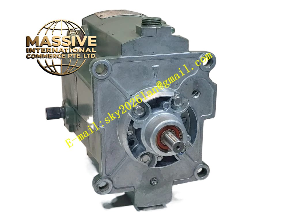
Description
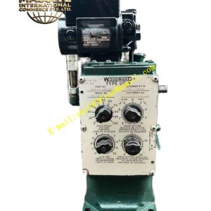
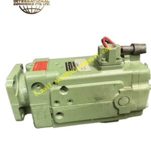
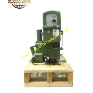
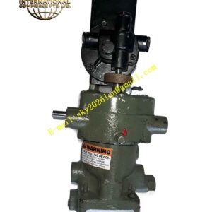
Woodward 8526-622
Technical Specifications
- Sensor Type: Passive magnetic pickup (variable reluctance).
- Output Signal: AC sine wave voltage proportional to rotational speed.
- Thread Size: Standard industrial thread for secure mounting in gear housings.
- Coil Resistance: Precision-wound coil with tightly controlled resistance specifications.
- Operating Temperature: Rated for continuous operation in extreme ambient temperatures.
Functional Features
- High Signal-to-Noise Ratio: Generates a strong voltage signal even at low cranking speeds.
- Vibration Resistance: Internally potted construction prevents coil damage from severe mechanical vibration.
- Wide Speed Range: Accurately tracks speed from idle to maximum overspeed conditions.
- Universal Compatibility: Interfaces seamlessly with all standard Woodward and third-party electronic governors.
Application Scenarios
Deployed in diesel engines, gas turbines, steam turbines, and any rotating equipment requiring precise speed measurement for governing or protection.
Performance Parameters
- Frequency Response: Linear output across the entire operational speed range.
- Air Gap Tolerance: Maintains signal integrity across specified air gap variations.
- Insulation Resistance: High dielectric strength to prevent signal leakage.
Material Composition
Features a durable stainless steel or hardened steel threaded body. The internal magnetic core and copper windings are encapsulated in a high-temperature epoxy resin for environmental protection.
Structural Characteristics
- Form Factor: Cylindrical probe with a standard hex wrench flat for installation.
- Termination: Shielded, twisted-pair lead wires with high-temperature insulation.
- Sealing: IP67 or higher rated sealing at the cable exit to prevent oil or moisture ingress.
Working Principle
As the gear teeth on the rotating shaft pass the tip of the magnetic pickup, they disturb the magnetic field, inducing an alternating voltage in the coil. The frequency of this AC voltage is directly proportional to the rotational speed of the shaft.
Installation Requirements
- Install with the exact air gap specified in the manufacturer’s manual (typically 0.020 to 0.050 inches).
- Use a non-magnetic feeler gauge for precise gap setting.
- Route the shielded cable away from high-voltage ignition or power cables.
Usage Precautions
- Never use metallic lock washers or conductive thread sealants that could short the sensor to the housing.
- Inspect the sensor tip periodically for metal debris accumulation, which degrades the signal.
- Replace immediately if the output signal becomes erratic or drops below minimum thresholds.