Description
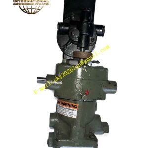
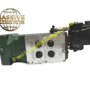
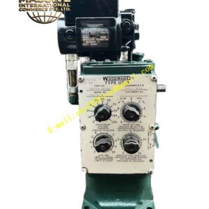
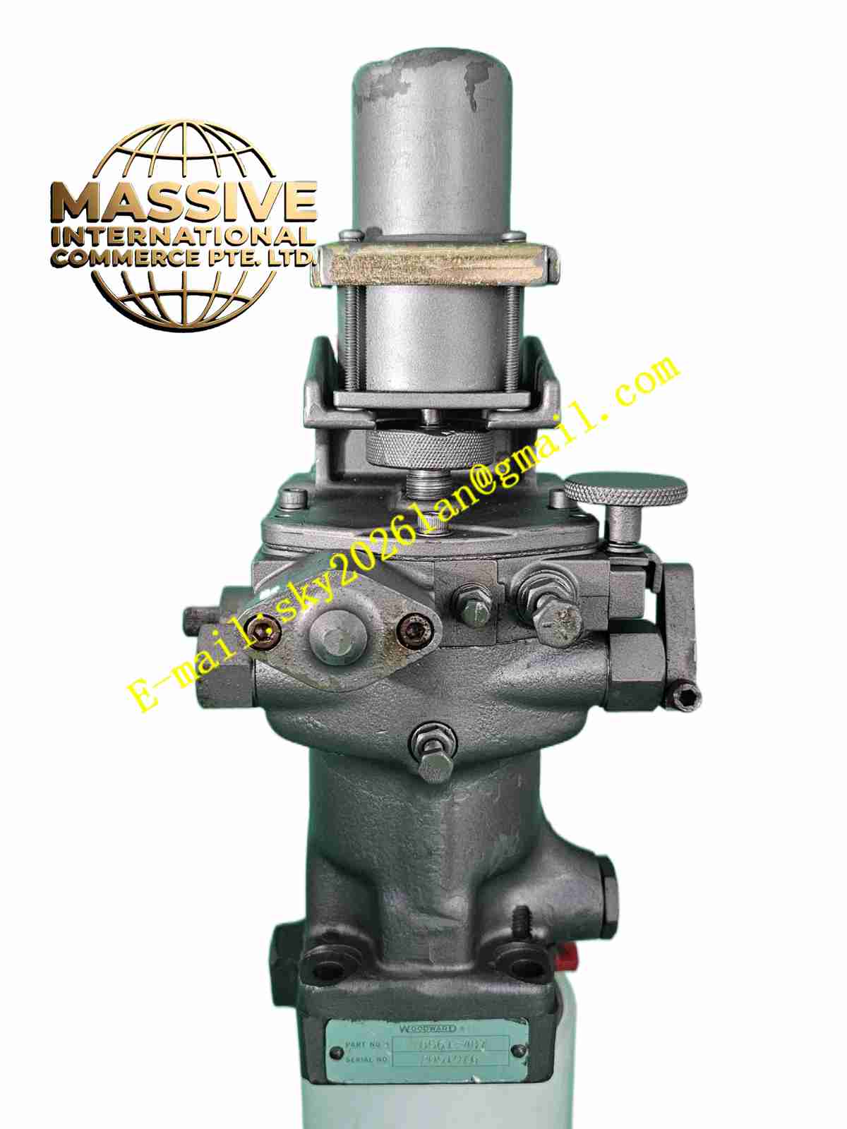
Woodward 8561-904
Technical Specifications
- Product Series: TG Series (Mechanical-Hydraulic Turbine Governor).
- Speed Setting Range: Typical adjustable range of 2400 to 4000 RPM.
- Output Torque: Capable of delivering up to 23.7 N·m (17.5 ft-lb) of output torque.
- Output Shaft Rotation: Maximum rotation angle of 40°, with a recommended operating stroke of 2/3 of the full travel from no-load to full-load.
- Lubrication: Compatible with standard 22/30 turbine oils.
Functional Features
- Self-Contained Design: Features an integrated oil pump and ball joint assembly, requiring no external power supply or hydraulic source.
- Speed Droop Control: Inherently provides speed droop characteristics, allowing for stable load distribution when operating in parallel with other generating units.
- Integrated Overspeed Test: Includes a built-in overspeed test device (OTSD) suitable for hazardous or ATEX explosion-proof environments.
- Direct Drive: Senses turbine speed directly via a drive shaft, ensuring immediate and accurate response to speed deviations.
Application Scenarios
Widely applied in industrial steam turbines, turbo-expanders, and mechanical drive applications (such as driving pumps and compressors) where reliable, standalone mechanical speed control is required.
Performance Parameters
- Operating Temperature: Functions reliably in extreme environments ranging from -40°C to +90°C.
- Speed Reduction: Rated speed reduction of approximately 2° at 4035 RPM.
Material Composition
Constructed with a robust cast iron or steel housing. Internal components, including the flyweights and pilot valve, are precision-machined from hardened steel to ensure long service life and wear resistance.
Structural Characteristics
A compact, flange-mounted unit weighing approximately 22 kg with dimensions of roughly 200×170×380 mm. It features a clockwise screw speed adjustment mechanism and standardized mechanical linkage output.
Working Principle
The governor is driven by the turbine’s output shaft. As the turbine’s speed changes, centrifugal force acting on internal flyweights causes them to move. This mechanical movement shifts a hydraulic pilot valve, which directs pressurized oil from the internal pump to a power piston. The piston adjusts the steam valve position to restore the turbine to the desired set speed.
Installation Requirements
Must be mounted securely to the turbine gearbox or accessory drive. The mechanical linkage connecting the governor output to the steam valve must be properly aligned to prevent binding. Ensure the drive shaft rotation matches the governor’s design specification.
Usage Precautions
- Regularly monitor the oil level and quality; change oil according to seasonal requirements (No. 22 in winter, No. 30 in summer).
- Inspect the mechanical linkage for wear and ensure smooth, friction-free movement.
- Never operate the turbine without verifying the governor’s overspeed trip functionality.