Description
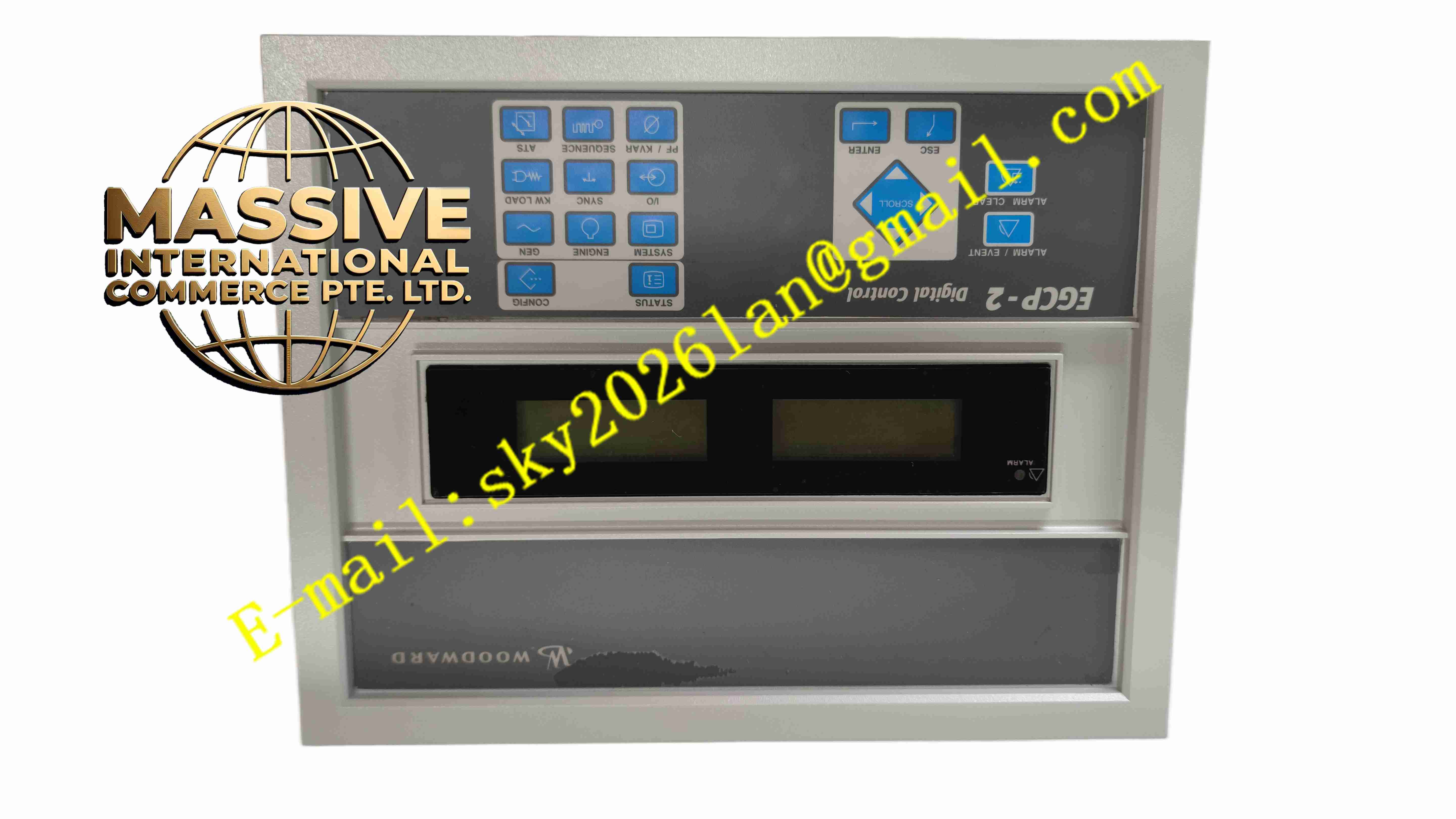
Woodward EGCP-2 8406-121
Technical Specifications
- Product Type: Digital generator set controller
- Supply Voltage: 12 VDC or 24 VDC battery supply
- Voltage Measurement: Single-phase or three-phase AC generator voltage
- Speed Sensing: Magnetic pickup speed signal input
- Output Drivers: Governor actuator driver and AVR control output
- Protection Functions: Over-speed, under-speed, overvoltage, undervoltage, overcurrent
- Communication: RS232 service port for configuration
- Protection Rating: IP30
- Operating Temperature: -40 °C to +70 °C
- Mounting: Panel or chassis mounting
Functional Features
- Automatic engine start and stop sequence control with configurable time delays.
- Generator speed regulation by driving engine fuel actuator.
- Generator voltage regulation via AVR control signal output.
- Comprehensive generator and engine fault protection with shutdown and alarm.
- Magnetic pickup input measures engine rotational speed directly from flywheel teeth.
- Front panel LED indicators display operating status and fault codes.
- RS232 service port for PC configuration and parameter upload/download.
- Configurable auxiliary relay outputs for alarm and status signaling.
- Built-in fault event log stores last shutdown cause for troubleshooting.
- Analog input channels monitor battery voltage and engine sensor signals.
Application Scenarios
- Small emergency backup generator sets
- Industrial prime power single genset units
- Mobile trailer generator control
- Pump engine control systems
- Simple remote site power generation equipment
Material Composition
- Housing: Die-cast aluminum alloy casing
- Main PCB: FR4 industrial circuit board with conformal coating
- Signal processing chips: High speed microcontroller and A/D converters
- Output power drivers: Power MOSFET and relay drivers
- Terminals: Copper alloy screw terminals
- LED indicators: Status LEDs for power, run and fault
Structural Characteristics
- Compact rectangular aluminum enclosure for chassis or panel mounting.
- Front panel with LED status indicators and fault code display area.
- Rear side terminal block for battery power, speed sensor, governor and generator wiring.
- Internal circuit separated into low voltage logic section and power driver section.
- Metal housing provides electromagnetic shielding.
- Multiple mounting holes for fixed installation.
Working Principle The controller receives battery power and monitors magnetic pickup speed signal and generator AC voltage. The internal microcontroller compares actual speed and voltage with setpoint values, outputs control signals to engine fuel actuator and generator AVR to stabilize frequency and voltage. It continuously monitors all measured parameters. When over-speed, under-voltage or other fault condition appears, the controller cuts fuel output and activates shutdown relay to stop engine, and stores fault code in memory. RS232 port connects to PC software for parameter configuration.
Installation Requirements
- Mount controller in dry, vibration-controlled cabinet or genset control box.
- Use shielded cable for magnetic pickup speed sensor wiring.
- Separate low signal sensor wiring from high current battery cables.
- Verify actuator wiring polarity before power on.
- Configure generator rated voltage, frequency and speed parameters via PC software.
- Perform engine start test and protection trip test after commissioning.
- Complete protective earth connection for aluminum housing.
Usage Notes
- Do not reverse battery polarity, reverse connection causes permanent hardware damage.
- Keep controller away from high temperature engine surface.
- Do not exceed maximum voltage and current rating of output drivers.
- Backup parameter file before firmware modification.
- Check speed sensor air gap and wiring integrity regularly.
- Disconnect battery before opening housing for inspection.
- Reset fault log only after root cause of shutdown is resolved.