Description
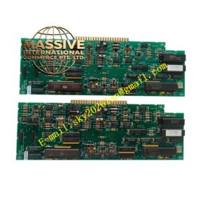
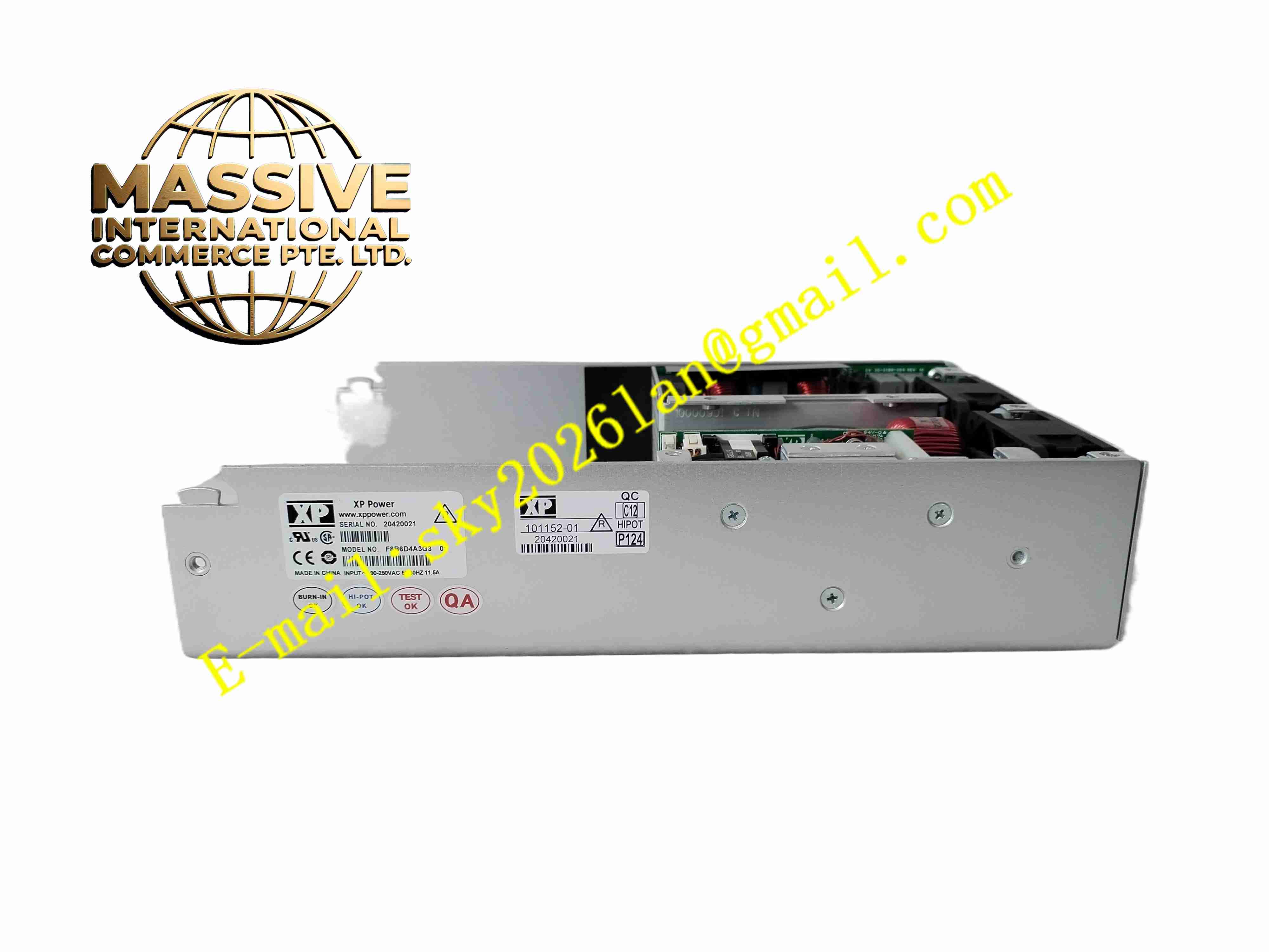
XP Power F8B6D4A3G3
Technical Specifications
- Product Type: Multi-output open frame switch mode power supply
- Input Voltage Range: 85VAC to 264VAC universal mains input
- Input Frequency: 47 Hz to 63 Hz
- Output Channels: Multiple isolated DC output rails
- Isolation: Reinforced isolation between primary and secondary side
- Protection Functions: Overvoltage protection, overcurrent protection, short circuit protection, over-temperature protection
- Efficiency: High efficiency conversion design
- Protection Rating: IP00 open frame construction
- Operating Temperature: -20 °C to +70 °C with derating
- Certifications: CE, UL, IEC60950
Functional Features
- Multiple independent isolated DC output channels supply different voltage requirements for embedded control hardware.
- Wide universal AC input range works with global mains voltage.
- Built-in comprehensive protection shuts down output automatically under fault conditions.
- Low ripple and noise output suitable for sensitive analog and digital circuits.
- Reinforced isolation barrier between high voltage input side and low voltage output side.
- Compact open frame design for integration inside custom equipment chassis.
- Power good signal output to host controller for power status monitoring.
- Convection cooling design without mandatory fan requirement at reduced load.
- Input inrush current limiting circuit reduces surge at power on.
- Low standby power consumption under no load condition.
Application Scenarios
- Industrial embedded controller internal power supply
- Custom machine control board power source
- Test and measurement equipment internal power
- Factory floor remote I/O station power supply
- Medical non-critical auxiliary control electronics
Material Composition
- Base plate: Metal steel mounting base plate
- Main PCB: FR4 printed circuit board
- Power components: High voltage electrolytic capacitors, IGBT and rectifier components
- Magnetic parts: High frequency transformers and inductors
- Input and output terminals: Solder pin or screw terminal connectors
- Insulation material: High temperature insulation film for transformer winding isolation
Structural Characteristics
- Open frame bare board and metal base plate construction for chassis mounting.
- High voltage primary circuit separated from low voltage secondary circuits on PCB layout.
- High frequency transformer provides galvanic isolation between input and outputs.
- Mounting holes on metal base plate for fixed installation inside equipment enclosure.
- Components arranged to optimize natural convection air flow.
- Output terminals located at one edge for wiring connection.
Working Principle AC mains input passes through input filter and rectifier circuit to produce high voltage DC bus. High frequency switching circuit drives main transformer to generate multiple secondary AC windings. Each secondary winding is rectified and filtered to produce stable isolated DC output rails. Feedback circuit monitors each output voltage and adjusts switching duty cycle to maintain constant output voltage. Protection circuits detect overvoltage, overcurrent and over-temperature and shut down switching operation when threshold is exceeded.
Installation Requirements
- Mount power supply inside closed metal equipment chassis with proper ventilation.
- Maintain minimum clearance between high voltage components and surrounding metal parts.
- Use proper wire gauge for input and output wiring.
- Complete protective earth connection to metal base plate.
- Separate input mains wiring from low voltage output signal wiring.
- Perform output voltage measurement and adjustment before connecting load.
- Verify earth continuity after installation.
Usage Notes
- Open frame unit must be installed inside protective enclosure to prevent touch of live high voltage parts.
- Do not operate beyond specified temperature and load derating curve.
- Do not short output terminals.
- Keep surface free of dust and conductive contamination.
- Disconnect AC input and wait for capacitor discharge before maintenance.
- Do not modify internal circuit components.
- Check output voltage periodically during long-term operation.