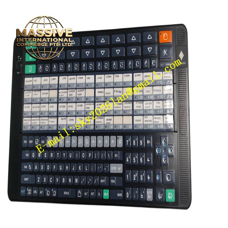
Description
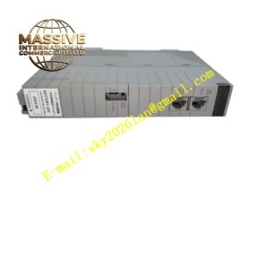
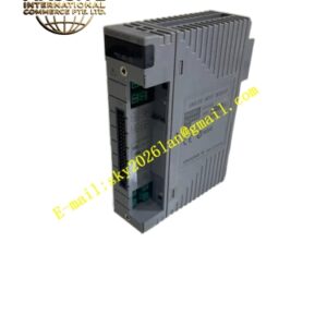
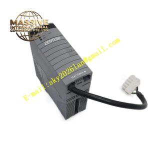
Yokogawa AIP831-101
Technical Specifications Multi-channel pulse input; supports contact pulse and voltage pulse signal types; maximum pulse input frequency up to 100kHz; 16-bit counting resolution; galvanic isolation between field and system backplane; 24V DC power supply; operating temperature -20°C to +70°C; IP20 protection class.
Functional Features Captures pulse signals from flow meters, speed sensors and pulse generators. Counts pulse quantity and calculates frequency to obtain flow rate, rotation speed and cumulative flow. Detects signal loss and abnormal pulse frequency and uploads fault alarms to the DCS. Supports configurable pulse weight and unit conversion for each channel. Transmits measurement data and diagnostic status to the controller via backplane bus.
Application Scenarios Oil and gas pipeline flow metering, water supply pipeline turbine meter monitoring, power plant turbine rotating speed measurement, chemical batch flow accumulation, natural gas metering stations.
Performance Parameters High pulse capture precision; low counting error under high-frequency pulse input; strong suppression of external interference pulses; continuous counting without data loss.
Material Composition PCB substrate is FR-4 flame-retardant multilayer printed circuit board; pulse acquisition and logic chips are high-speed industrial semiconductors; isolation circuits use optocoupler devices; backplane gold finger contacts use gold-plated copper alloy; module shell is flame-retardant engineering plastic; terminal contact parts are nickel-plated copper alloy.
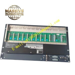
Structural Characteristics Vertical plug-in module for Yokogawa DCS racks. Front panel has power, communication and channel fault LED indicators. Rear gold finger connector connects to rack backplane for power and bus communication. Front terminal blocks receive pulse signal wiring from field sensors. Mechanical locking clip prevents loosening caused by cabinet vibration.
Working Principle Field pulse signals pass through signal conditioning and isolation circuits. The onboard hardware counter captures each rising or falling edge of pulses. The processor calculates frequency and cumulative values according to configured pulse coefficients. Measurement data and fault information are sent to the DCS controller over the backplane bus.
Installation Requirements Power off the DCS rack before installing the module. Insert the module into the corresponding rack slot and lock the retaining clip. Use shielded twisted-pair cables to connect pulse sensors to module terminals. Set pulse coefficient, signal edge type and alarm thresholds in Yokogawa engineering software. Test pulse counting function on site after wiring.
Precautions for Use Route pulse signal cables away from high-power inverter cables. Confirm the signal voltage level matches module input specifications. Do not apply overvoltage to pulse input terminals. Perform regular calibration of pulse metering channels for custody transfer applications.