Description
ZYGO ZMI4104
Technical Specifications: Mechanical form‑factor: 6U VME64x board; measurement channel count: 4 independent axes; position resolution 0.154 nm; maximum measurable velocity ±2.55 m/s; maximum measurement range determined by matched optical interferometer hardware; minimum acceptable optical input power 1.0 µW; compatible laser heads: ZYGO 7702, 7714, 7724 series helium‑neon heterodyne laser sources; built‑in patented cyclic‑error compensation algorithm; data interfaces: VME64x bus, high‑speed serial HSSDC daisy‑chain connector for multi‑board synchronization; operating temperature 10 °C‑40 °C; storage temperature ‑20 °C‑70 °C; relative humidity 20‑80 %RH non‑condensing; weight 420 g; signal‑quality monitoring function for each optical input channel.
Functional Features: Four independent high‑resolution interferometer measurement channels on single VME board; patented cyclic‑error compensation automatically suppresses inherent non‑linear measurement errors of heterodyne interferometer systems; per‑channel optical signal‑strength monitoring reports optical power level and signal‑to‑noise ratio; high‑speed HSSDC daisy‑chain interface achieves precise multi‑board axis synchronization; VME64x bus transfers displacement measurement data to host VME CPU for closed‑loop motion‑control processing; supports mixed‑mode channel configuration for displacement measurement, pitch/yaw tilt error compensation and reference interferometry tasks; measurement data output supports real‑time integration with high‑speed motion‑controller closed‑loop positioning systems.
Application Scenarios: Semiconductor lithography wafer‑stage position metrology; ultra‑precision nano‑positioning stage closed‑loop feedback; optical component manufacturing inspection equipment; aerospace precision component calibration systems; high‑end coordinate measuring machinery; multi‑axis ultra‑precision motion equipment requiring nanometer‑level position feedback.
Performance Parameters: Typical measurement sigma accuracy reaches 0.2 nm at maximum tracking velocity; cyclic‑error compensation reduces interferometer non‑linear error down to system noise floor level; multi‑board synchronization maintains sub‑nanosecond timing alignment across daisy‑chained boards; supports continuous high‑speed dynamic displacement tracking under rated optical input‑power conditions.
Material Composition: FR‑4 high‑precision multilayer glass‑fiber printed‑circuit board; heterodyne signal‑processing analog and digital integrated circuits; high‑speed VME64x bus interface chips; optical signal receiver photodiode assemblies; HSSDC high‑speed serial connector; gold‑plated VME64x backplane edge‑connector contacts; multi‑color SMD status LED indicators; metal VME front‑panel with ejector latch handles.
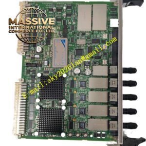
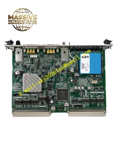
Structural Features: Standard 6U VME64x board geometry with front‑panel ejector latches for chassis insertion and extraction; rear‑side gold‑plated VME64x edge‑connector mates with VME chassis backplane bus; front‑panel mounts HSSDC daisy‑chain synchronization connector and status‑LED indicators; optical signal input cables connect directly to onboard photodiode receiver assemblies on board component side; ejector‑latch mechanism facilitates safe insertion and removal inside VME chassis.
Working Principle: Heterodyne laser beams reflected from measurement target interferometer optics produce phase‑shifted optical signals directed onto ZMI4104 onboard photodiode receivers. Photodiodes convert optical interference signals into high‑frequency analog electrical signals. Analog front‑end circuits process heterodyne beat‑frequency signals, extracting phase difference proportional to target‑mirror displacement. Digital logic executes patented cyclic‑error compensation algorithm to remove inherent interferometer non‑linear errors. Calculated high‑precision displacement values are stored in board registers and transferred to host VME CPU via VME64x bus. HSSDC daisy‑chain port distributes timing reference clock signal across multiple ZMI4104 boards to guarantee synchronous sampling for multi‑axis measurement systems.
Installation Requirements: Power off VME chassis completely before inserting ZMI4104 board; use front‑panel ejector latches to seat board fully into 6U VME chassis slot; tighten front‑panel mounting screws for mechanical fixation; route optical fiber or free‑space optical paths strictly following ZYGO optical alignment specifications; separate measurement electronics signal cables from high‑power motor and drive power cables; VME chassis must implement reliable protective grounding.
Usage Notes: Hot‑insertion of ZMI4104 board inside powered‑on VME chassis is strictly forbidden; maintain optical input power within specified operating window for each channel; protect photodiode receiver components against excessive incident laser power; avoid deployment in environments with condensation, dust accumulation or corrosive vapor; perform optical‑path alignment and signal‑quality verification during system commissioning; keep VME chassis operating temperature within 10 °C‑40 °C range.