Description
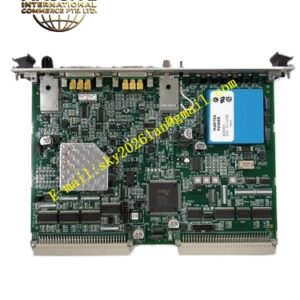
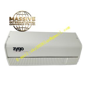
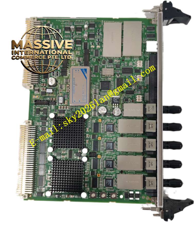
ZYGO ZMI4104
Technical Specifications
- Board Architecture: 6U VME64x Standard Form Factor
- Measurement Channels: 4 Independent, Synchronous Axes per Board
- Position Resolution: 0.15 nm (Sub-nanometer)
- Maximum Measurement Velocity: ±2.55 m/s
- Accuracy at Max Velocity (σ): 0.2 nm
- Minimum Optical Power: 0.07 µW
- Power Supply: 24V DC (±10% tolerance)
- Power Consumption: 45W Maximum
Functional Features
- Patented Cyclic Error Compensation: Automatically and seamlessly eliminates non-linear cyclic errors intrinsic to displacement interferometry, pushing error terms into the measurement noise floor for ultimate precision.
- Modular Scalability: Supports VME chassis backplane integration, allowing multiple boards to be stacked to expand system capacity up to 64 measurement axes without external gateways.
- Real-Time Closed-Loop Control: Measurement data is output directly to motion controllers with ultra-low latency, enabling high-bandwidth servo loops for nano-positioners.
- High Signal-to-Noise Ratio: Advanced phase measurement electronics ensure high precision and eliminate false counts, even at zero slew rates or during direction reversals.
- Built-In Diagnostics: Front-panel LEDs provide immediate visual status for power, communication, and individual channel health, facilitating rapid troubleshooting.
Application Scenarios
- Semiconductor Lithography: Critical for wafer stepper and scanner stage positioning, e-beam mask writers, and optical steppers requiring nanometer-level overlay accuracy.
- Metrology & Inspection: Used in CD-SEMs, wafer inspection tools, and LCD measurement equipment for precise stage calibration and movement verification.
- Precision Manufacturing: Die bonders, drilling tools, memory repair tools, and probers where absolute position feedback is mandatory.
- Scientific Research: Gravitational wave detection, synchrotron beamline positioning, and ultra-high vacuum experimental setups.
- Aerospace & Defense: Precision assembly of optical systems, satellite component alignment, and inertial navigation system calibration.
Performance Parameters
- Linearity Error: < ±0.1 ppm (Parts Per Million)
- Update Rate: 100 kHz per Channel
- Data Interface: EtherCAT, RS-422, USB 3.0
- Environmental Compensation: Integrated Edlen equation calculation for real-time refractive index correction based on air temperature, humidity, and pressure.
- Vibration Immunity: 0.5g (5-500 Hz per ISO 10816-3)
- Electromagnetic Compatibility: Compliant with EN 61326-1 Industrial Standards
Material Composition
- PCB Substrate: High-Tg, Multi-layer FR4 with Gold-plated VME64x Edge Connectors for reliable high-speed data transmission.
- Optical Interface: Precision Ceramic Ferrule Connectors for Fiber Optic Input, ensuring long-term alignment stability and low insertion loss.
- Thermal Management: Aluminum Heat Spreaders and Thermal Vias on critical FPGA and DSP components to maintain junction temperatures within safe limits.
- Conformal Coating: Acrylic or Parylene coating on non-connector areas to protect against humidity, dust, and chemical vapors in cleanroom or industrial environments.
Structural Characteristics
- Form Factor: Standard 6U VME64x Eurocard (185 mm × 135 mm × 28 mm).
- Weight: Approximately 0.68 kg.
- Front Panel: Dedicated Fiber Optic Input Ports (LC/PC or similar), Status LED Array, and Test Points.
- Backplane Interface: Full VME64x pinout supporting high-speed parallel data transfer and control signals.
- Mounting: Standard VME wedge locks and front panel extraction handles for secure chassis installation and safe removal.
Working Principle
The ZMI-4104 utilizes Heterodyne Interferometry. It receives two-frequency laser light from a ZMI™ Laser Head (e.g., 7702, 7714, 7724) via optical fiber. The board’s photodetectors convert the optical interference pattern into electrical signals. An onboard FPGA/DSP architecture demodulates these signals to extract phase information, which is directly proportional to displacement. The Cyclic Error Reduction algorithm processes the quadrature signals to correct non-linearities, while environmental sensors feed data into the Edlen Equation engine to compensate for air refractive index changes, outputting a true vacuum-equivalent displacement value.