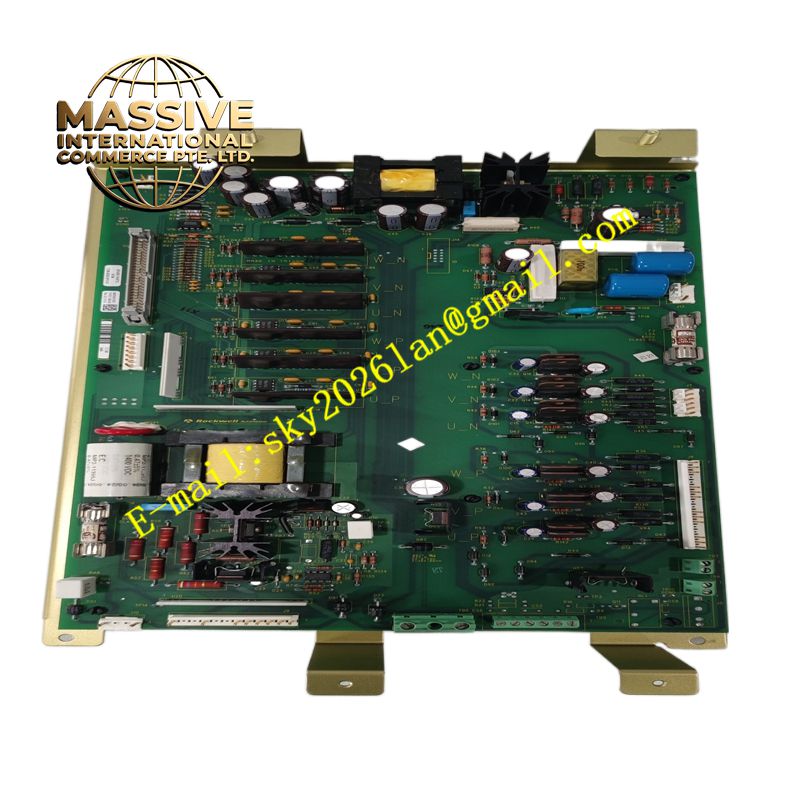
Description
A-B 1336-BDB-SP31D
Technical Specifications Designed for matching Allen‑Bradley 1336 series AC drives; built‑in power resistor bank with defined resistance and continuous power rating; integrated thermal cutout protection circuit; high power pulse energy absorption capacity; compatible with dedicated drive braking control logic; terminal block for power wiring and thermal feedback connection.
Functional Features Absorbs regenerative energy fed back to the DC bus from induction motors. Provides controlled rapid deceleration for high inertia mechanical loads. Embedded thermal protection shuts down operation once overtemperature thresholds are reached. Hardwired thermal alarm signals transmit fault status back to the host drive. Reduces drive overvoltage trips during stop sequences and downhill load operation.
Application Scenarios Conveyor systems, material elevators, large centrifugal fans, rotary positioning tables and crane auxiliary motion axes controlled by Allen‑Bradley 1336 variable frequency drives.
Performance Parameters High peak energy dissipation capability; stable resistance value across operating temperature range; fast thermal fault response; durable power dissipation under cyclic braking duty cycles.
Material Composition Power resistors use wound alloy resistance wire with ceramic insulation; mounting base is coated steel; internal wiring uses high‑temperature silicone insulated wire; terminal block housing is flame retardant thermoplastic; thermal switch assembly sealed with heat resistant potting compound.
Structural Characteristics Compact enclosed metal chassis structure; external mounting lugs for cabinet installation; front access terminal strip for power and feedback wiring; internal air flow channels for passive convection cooling; thermal sensing components directly attached to resistor assemblies.
Working Principle When the motor decelerates, it operates as a generator and feeds electric energy back into the drive DC bus. The drive’s braking IGBT switch activates and connects this resistor module across the DC bus. Current flows through the alloy resistor elements and converts electric energy into heat. The thermal switch monitors resistor temperature and triggers fault signals if overheating occurs.
Installation Requirements Mount the module vertically inside a ventilated electrical cabinet to maintain proper convection cooling. Leave clear spacing around the unit to avoid heat accumulation. Route power cables in accordance with drive current ratings. Connect the thermal protection feedback wiring to the designated braking fault terminals of the 1336 drive.
Precautions for Use The module surface reaches high temperatures during braking events. Do not touch the enclosure while the system operates or immediately after shutdown. Maintain clearance from sensitive low power electronic components. Do not modify internal resistor wiring or bypass thermal protection circuits.