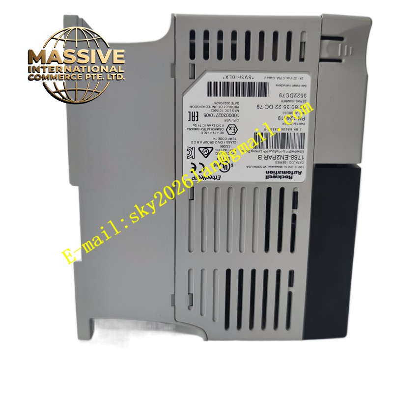
Description
A-B 1788-EN2PAR
Technical Specifications Dual independent Ethernet ports; supports Ethernet/IP industrial protocol; parallel redundant network logic; 24V DC auxiliary power supply; status LED indicators for each network channel; DIN rail mounting form factor.
Functional Features Establishes redundant communication paths for control and I/O data. Automatically switches data transmission to the healthy network channel upon cable or port failure. Transfers real time I/O messages, controller tags and diagnostic information between network domains. Provides network health status data to the host control system. Supports network address configuration via Rockwell automation software tools.
Application Scenarios Critical manufacturing production lines, power plant auxiliary control systems, material handling safety systems and redundant PLC control architectures requiring uninterrupted Ethernet communication.
Performance Parameters Fast network switchover time; low communication latency; consistent real time data throughput; stable operation under industrial electromagnetic interference.
Material Composition Enclosure is flame retardant thermoplastic; internal circuit board is FR‑4 multilayer PCB; Ethernet connector contacts are gold plated; power terminals are nickel plated copper alloy; internal communication chips are industrial wide temperature grade.
Structural Characteristics Compact rectangular DIN rail mount housing; front panel fitted with Ethernet RJ45 connectors and multi‑color status LEDs; removable screw terminal block for 24V DC power input; DIN rail clip integrated on the rear casing.
Working Principle The device receives Ethernet/IP packets from the host controller network. It duplicates data streams across two independent Ethernet ports. Continuous health checking runs on both communication links. When one communication path fails, the unit routes all control traffic through the remaining functional port without disrupting controller and remote I/O interaction.
Installation Requirements Clip the unit onto standard 35mm DIN rail inside a control cabinet. Wire 24V DC power supply to the designated power terminals. Connect each Ethernet port to separate network switches for redundant topology. Configure network parameters using Rockwell Studio5000 or network configuration software.
Precautions for Use Use industrial grade shielded Ethernet cables. Separate network wiring from high power motor cables. Do not operate the device outside rated ambient temperature limits. Verify redundant switchover logic during commissioning before placing the system into production service.