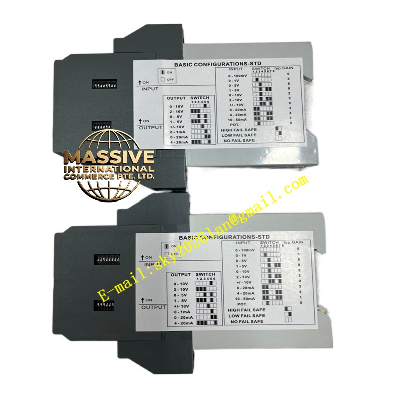
Description
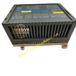
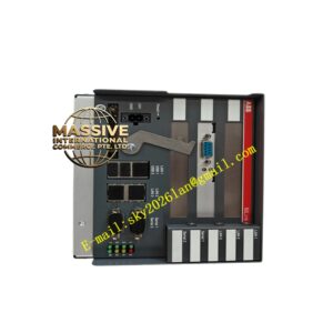
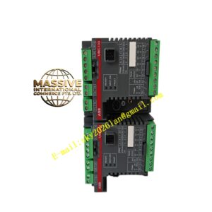
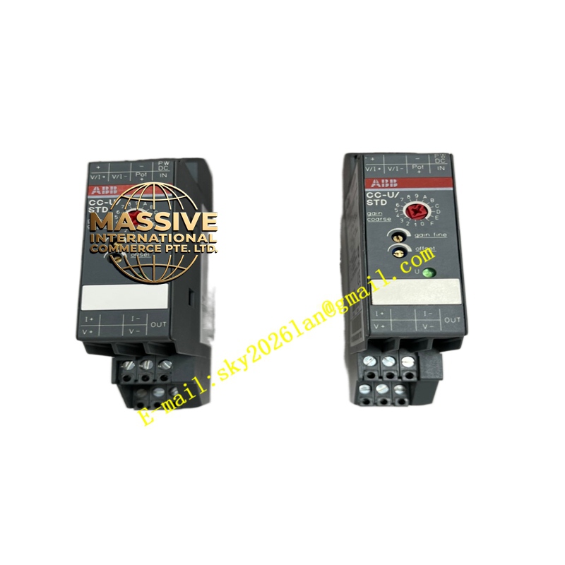
ABB 1SVR040000R1700
- Technical Specifications (typical CM-SVS 200–480 V version):
- Monitored Voltage: 3 × phase-phase (L1-L2, L2-L3, L3-L1), 200–480 V AC ±10 % (some allow 100 V with different stock no.)
- Undervoltage Setting (U<): 80–95 % of measured avg (or absolute V — pot calibrated)
- Overvoltage Setting (U>): 105–120 % of avg (absolute pot)
- Phase Loss Detection: Yes — any phase falling >asym threshold (typ. 15–20 % asym) triggers fault
- Phase Sequence Check: Yes — incorrect (ACB/CBA) → fault
- Hysteresis: ≈2–5 % of setpoint (prevents chatter near threshold)
- Output Contact Rating: 5 A @ 250 V AC (resistive), 5 A @ 30 V DC
- Power Consumption: ≤3 VA (from monitored supply)
- Operating Temp.: –20 °C to +55 °C (–40 °C to +70 °C storage)
- Protection Degree: IP20 (terminals), IP40 (front with cover)
- Certifications: CE, UL 508, cULus, GL (marine), CCC
- Dimensions: 22.5 mm (W) × 90 mm (H) × 70 mm (D) — 1 C/O version; 45 mm W for 2 C/O
- Functional Features:
- Self-powered from monitored 3-phase supply — no external 24 V DC required (convenience & ensures monitoring stops if supply lost → relay drops out = safe)
- Adjustable time delay (0.1–10 s) on some CM-SVS variants to avoid nuisance trip during brief sags (e.g., motor start inrush sag)
- Clear LED status — quick fault diagnosis (which condition tripped: UV, OV, Phase Loss, Wrong Seq)
- DIN-rail clip — snaps beside contactors, drives, PSUs in MCC
- Application Scenarios:
- MCC Incoming Feeder Monitor: Before closing main MCC contactor — CM-SVS checks supply healthy; if UV/OV/phase loss → inhibits close or trips main contactor
- VFD / Soft Starter Supply Supervision: Prevent drive start on unhealthy supply (UV may cause drive rectifier overcurrent; OV may stress DC link caps); wire CM-SVS NC contact in series with drive “Enable” or “Run Permissive”
- Generator Output Check Prior to Paralleling: Verify gen V & seq correct before closing GCB (with LS-5 synch relay doing fine sync)
- UPS Bypass Source Monitor: Ensure bypass line healthy before transferring load
- Material & Structure:
- Housing: Gray polyamide (PA66), UL 94 V-0, self-extinguishing
- Terminals: Screw-type (M3) — accept 0.2–2.5 mm² solid/flex; strap & ferrule OK
- Front: Transparent hinged cover (removable) protecting pots & LEDs
- DIN clip: Zinc-plated steel, 35 mm EN 60715
- Working Principle:
Internal voltage dividers step down L-L voltages → rectify & sample → microcontroller computes RMS of each phase & average. If:
- Any L-L RMS < U< setpoint → Undervoltage fault
- Any L-L RMS > U> setpoint → Overvoltage fault
- Phase angles not 120° ±5° (wrong seq) → Sequence fault
- One phase significantly lower (>asym threshold) vs other two → Phase Loss fault
Any fault → relay de-energizes (fail-safe) after optional time delay; healthy → relay picks up. On supply loss → relay drops (safe).
- Installation Requirements:
- Mount on 35 mm DIN rail in MCC / panel — leave space above/below for wiring
- Connect L1, L2, L3 to terminals marked U, V, W (phase-phase monitoring — NOT phase-neutral unless using CM-SVS-UNI 100 V version)
- Connect output relay contacts:
- 11–12–14 (C–NC–NO): Typical use = NO (14–12) in series with “Start Permissive” / “Drive Enable” — healthy → contact closes → allows start/run; fault → opens → inhibits/ trips
- Optionally use NC (11–12) for alarm annunciation
- Adjust UV/OV pots with flat-blade screwdriver — use test voltage source or live (caution!) to verify trip points before final energizing load
- Verify LED behavior: Green ON = healthy; Red ON = fault condition active
- For time-delay version: set delay pot — e.g., 0.5 s to ride through brief sags from other large motor starts on same feeder
- Precautions:
- Self-Powered Implication: If supply is completely lost (all 3 phases dead) relay drops — correct fail-safe; BUT if only one phase lost → still partially powered — will detect phase loss & drop. Ensure wiring L1/L2/L3 from same source being monitored.
- Do NOT apply >480 V L-L to 200–480 V version — overvoltage may damage dividers (there is a 100–130 V version for PT secondaries — use that for VT monitoring)
- For VT secondaries (e.g., 100 V L-L from 11 kV PT) — order CM-SVS 100–130 V AC version (different stock number — NOT this 200–480 V one)
- Time delay set too long may mask sustained UV — balance: long enough to avoid nuisance (0.2–0.5 s typical) but short enough to trip before equipment damaged by sustained UV (drive undervoltage trip usually faster — CM-SVS mainly for start permissive)
- Test after install: simulate UV by lowering input V (variac) → confirm relay drops at setpoint; simulate phase loss (disconnect one phase) → confirm drop