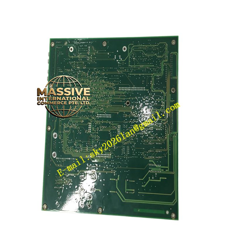
Description
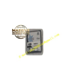
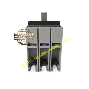
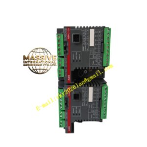
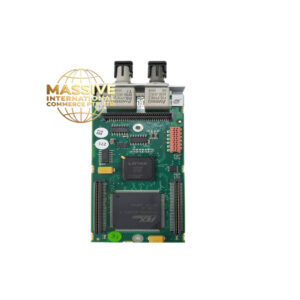
ABB 3ASC25H203
- Technical Specifications (SPDO13 Relay DO — typical):
- Output Channels: 8 (1 group or 2 groups ×4)
- Contact Type: SPDT (form C) or SPST-NO (form A) — common = SPDT
- Contact Rating: 2 A @ 250 V AC (cos φ=1), 2 A @ 30 V DC resistive; min. load 10 mA
- Switching Voltage: ≤250 V AC / ≤125 V DC
- Response Time: ≤10 ms operate / ≤5 ms release
- Isolation: 1500 V AC ch-group ↔ bus
- Power: From S100 bus (5 V logic + 24 V excitation via SPU01 PSU)
- Indicators: Run LED (green), Err LED (red), Output Active LED per ch
- Mounting: On S100 termination unit (TA563 etc.) — DIN 35 mm
- Operating Temp.: 0 °C to +55 °C
- Dimensions: ≈45 mm (W) ×119 mm (H) ×102 mm (D) — 1 S100 module width
- Certifications: CE, UL, cUL, marine (DNV etc.)
- Functional Features / Application / Material / Structure / Working Principle / Installation / Precautions:
- Wire field load (e.g., interposing relay coil, alarm beacon, solenoid valve) between COM & NO (or NC for fail-safe) terminals
- In Advant / AC800M+S100 Config: assign module type = SPDO13 → DO address → download → force ON/OFF from controller to test
- Precaution (Relay Life): Mechanical life ≈10⁷ ops; electrical life ≈10⁵ ops at rated load — for frequent switching (>几次/秒 or >数万次/年) consider transistor DO module (SPDO23) or interpose SSR. For inductive DC loads (solenoid/relay coil) use flyback diode or RC snubber across load to protect contacts.
- S100 bus must be terminated (95 Ω at last node) & PSU (SPU01) sized for ∑ module logic + output load coil current (relay coil current drawn from UP terminal — not from bus 5 V but from 24 V UP — still count in PSU sizing)
- If module is actually a comm card (CI520A S100 I/F) with 3ASC25H203 as material no. — then refer to earlier TC514V2 (CI520A) description — it’s the bus master for AC800M/Advant 450.