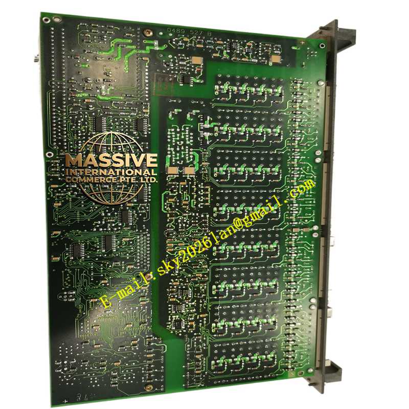
Description
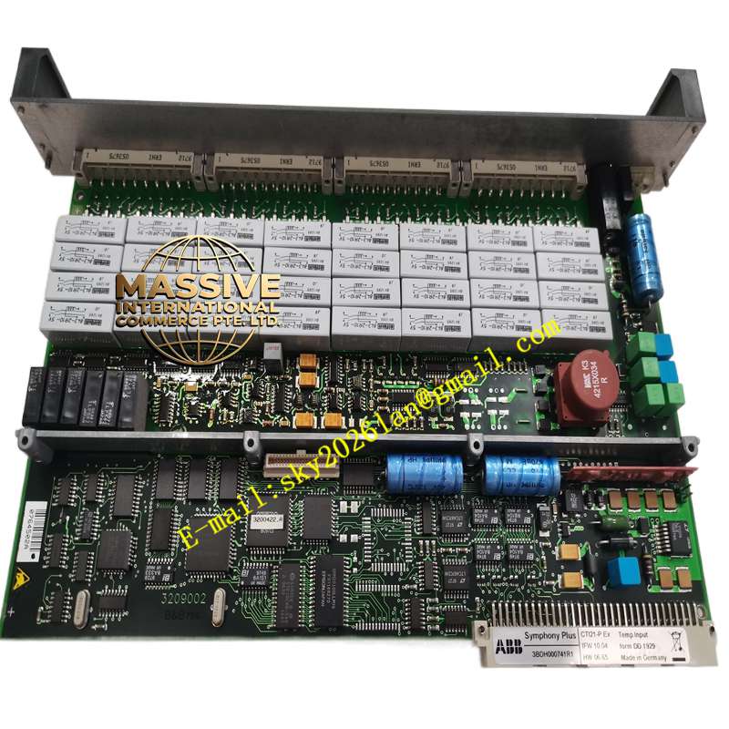
ABB 3BDH000741R1
- Technical Specifications (typical AI835A — “A” = latest hardware revision with improved EMC & CJC):
Number of Channels: 8 (differential), grouped as 2 × 4
Input Types (per ch, software selectable):
Thermocouple: J, K, T, E, N, R, S, B (linearized per IEC 60584; CJC ±0.5 °C typ.)
RTD: Pt100 (α=3850 / 3926 ppm), Pt200, Ni100 — 2-wire / 3-wire / 4-wire (3-wire recommended for best accuracy)
Voltage: ±10 V, 0–10 V, ±5 V, 0–5 V (impedance >1 MΩ)
Current: ±20 mA, 0–20 mA, 4–20 mA (via 250 Ω internal shunt — externally jumperable on TB567 terminal block)
Resolution: 16 bit (0.0015 % FS)
Accuracy (typical @25 °C):
Voltage / Current: ±0.1 % of reading
TC (incl CJC): ±0.5 °C + TC class tolerance B
RTD: ±0.2 °C + sensor tolerance
Input Impedance:
Voltage mode: >1 MΩ
Current mode: 250 Ω (internal shunt — terminal block must have jumper set to “mA” position to connect shunt)
Conversion Time: ≈20–40 ms per channel (scan all 8 ch ≈160 ms typical — configurable dwell)
Isolation: 500 V AC rms ch-group ↔ backplane; 50 V AC ch-group ↔ ch-group
Power Requirement: 5 V DC from S800 backplane (via PPD113) — typ. 150 mA; 24 V DC UP (process voltage) for term-block excitation if required by some sensors (RTD 3-wire loop excitation from UP or from AI835 internal — configurable)
Indicators: Run (green — module active in I/O scan), Err (red — fault / config mismatch / wire break), Warning (amber — minor diag like slight overrange)
Mounting: On S800 termination unit (TB521 / TB511) — DIN 35 mm; hot-swappable (with controller scan active)
Operating Temp.: 0 °C to +55 °C (–40 °C to +70 °C storage)
Certifications: CE, UL, cUL, ATEX Zone 2 (with system cert), marine (DNV/ABS/LR/BV)
Dimensions: 45 mm (W) × 119 mm (H) × 102 mm (D) — 1 S800 module width
Functional Features:
Per-channel configuration: type, range, alarm limits (Hi / Lo / HiHi / LoLo with latching), deadband, simulation value, filter time constant
Cold-Junction Compensation (CJC): Two CJC sensors (one per 4-ch group) measure terminal block temp → TC EMF referred to 0 °C
Open-sensor detection: For RTD & mA — if loop broken → value drives to configured burn-out direction (e.g., 3.6 mA / 21.5 mA for 4–20 mA upscale burnout) → controller can detect sensor failure
Process Alarm: High / Low / Deviation alarms evaluable in controller or locally (if using faceplate alarm processing in 800xA)
Module Replacement without Recalibration: New AI835 auto-loads config from controller on insertion (hot-swap) — no manual dip-switch setting
Application Scenarios:
Process Temperature Measurement: Reactor temp (TC type K/S), steam header (RTD Pt100), bearing temp (TC T/J)
Pressure / Flow / Level Secondary Instruments: 4–20 mA from smart Tx (pressure, dp-flow, level) — though AI801 cheaper if ONLY mA/V needed; AI835 used when TC/RTD also present in same rack
Analyzer / Lab Signals: ±10 V from chromatography or pH meter (high-res)
Retrofit of legacy analog input cards in Advant / S100 I/O → S800 I/O migration keeps same field wiring (via TB567 terminal block on TA563/TA566)
Material & Structure:
Housing: Gray polyamide (PA66), UL 94 V-0, with label pocket for module tag
Front: Transparent window showing Run/Err/Warning LEDs
Edge Connector: Gold-plated 30-pin (mates with TB521/TB511 bus bars)
Required Terminal Block: TB567 (analog terminal block) — snaps onto TA563/TA566; has screw terminals for Tc/RTD/mA/V wiring + shunt jumpers (mA / V select)
Internal: 16-bit sigma-delta A/D per channel group, galvanic isolation barriers, CJC sensor (NTC thermistor) on each group’s terminal block landing area
Working Principle:
Field sensor (TC/RTD/mA/V Tx) wired to TB567 screw terminals → signal conditioned (filtered, amplified, shunt for mA) → fed to 16-bit A/D converter
For TC: A/D measures EMF relative to CJC sensor temp (read from NTC on TB567) → final temp = f(EMF, CJC_temp, TC linearization table)
For RTD: A/D measures voltage drop across RTD (excited by small current — sourced either from AI835 internal or from UP terminal per jumper) → compute resistance → convert to temperature via Callendar–Van Dusen eqn
Converted value stored in module’s input image → transmitted to AC 800M controller each I/O scan via ModuleBus/HN800
If wire break / overrange → module sets diagnostic bit & optionally forces substituted value (last good / user-defined)
Installation Requirements:
Mount TB521/TB511 on DIN rail → install PPD113A01 (left end) → connect 24 V DC
Snap TB5