Description
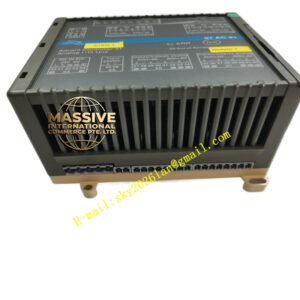
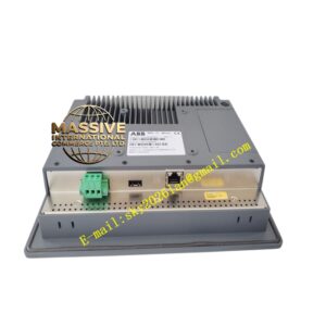
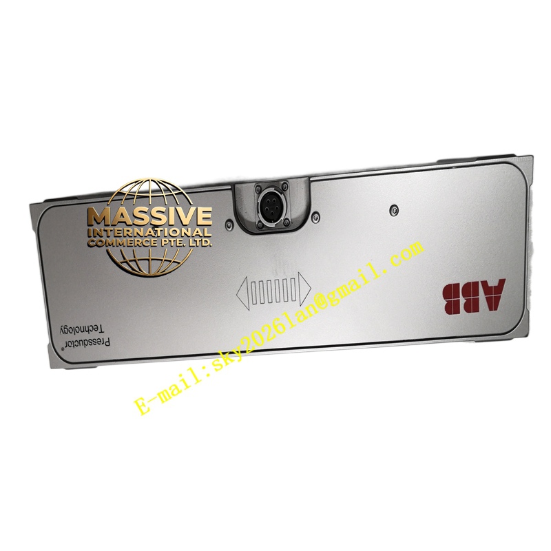
ABB PFTL201C 10KN 3BSE007913R10
- Working Principle (Magnetoelastic / Villari Effect):
- AC excitation (V_exc, typically 10 V rms @ 2–5 kHz) applied to primary winding from PFEA amplifier → establishes alternating magnetic flux in ferromagnetic core
- Applied compressive force F along cell axis → alters domain alignment → changes magnetic permeability μ(F) → induces proportional secondary voltage V_sig(F) in measurement winding (V_sig ∝ μ(F) × V_exc)
- PFEA amplifier measures V_sig (synchronously demodulated) → linearizes per stored calibration (Sensitivity S in mV/V) → computes Force = (V_sig / V_exc) × (Rated Force / S)
- Tare (zero) subtracts no-load offset (recorded with web slack / roll lifted)
- Scaled output (4–20 mA, ±10 V) sent to DCS / tension controller; alarm relays evaluate web-break (<Break % FS for >Break Time) & overload (>Overload % FS)
- Installation Requirements:
- Prepare Mounting Seats: Top & bottom reaction plates (or load shoes) must be flat (≤0.02 mm/mm flatness), parallel, free of burrs / weld spatter. Surface hardness ≥HB 200 (mild steel OK).
- Position Cell: Place PFTL201C between seats — align dowel pins on cell with matching holes in seats — tighten set screws / clamp plates to specified torque (AB doc — typically just enough to prevent slip; do NOT overtighten — cell must be free to compress axially)
- Important: The cell is loaded only through its end faces — dowel pins locate but do NOT carry load; body must not contact surrounding structure (clearance ≥1 mm)
- Connect Cable: Run shielded twisted pair (Excite+/–, Sig+/–) + shield drain wire → terminate in PFEA amplifier:
- Excite+ → PFEA Excite+
- Excite– → PFEA Excite–
- Sig+ → PFEA Sig+
- Sig– → PFEA Sig–
- Shield → PFEA Shield terminal → bond to panel PE bus (star ground — one end only, at PFEA side)
- Verify Excitation Match: In PFEA menu select excitation voltage / frequency matching cell spec (typically 10 V rms / 2.5 kHz for PFTL201C — check nameplate / cert)
- Power Up PFEA: Check Signal Level bar graph on PFEA — with no load should read near zero (after tare) or small offset (record as tare value)
- Perform Tare: With web cut / roll lifted (zero tension on cell) → press Tare on PFEA → stores offset. Verify reading = 0 (or near 0 within noise)
- Calibrate Full Scale: Either enter known FS (10 kN) in PFEA — or if a known calibrated weight / dead-weight can be hung / rolled across → verify mA output corresponds (e.g., 5 kN → 12 mA for 4–20 mA = 0–10 kN)
- Set Alarms: Web Break LoLo (e.g., <5 % FS for >0.2 s) → Web Break relay; Overload HiHi (e.g., >110 % FS) → Overload relay
- Document: Record cell Serial #, Calibration Sensitivity (mV/V), FS value (10 kN), tare reading, install date — keep Calibration Certificate on file
- Use & Precautions:
- Pure Axial Loading Only: Side loads, bending moments, torque on cell → error & possible damage. Use proper seats & dowel pins. Never restrain the cell body laterally.
- No Preload via Clamping: Clamping bolts / plates locate the cell — they must NOT apply compressive preload. Preload is introduced only by the process force (web tension / press force).
- Shield Grounding: Single-point ground at PFEA — if frame is also grounded (usual) do NOT ground shield at cell end (may already be capacitively coupled via frame — fine, but do NOT add second drain wire bond at cell). Check for ground loops if noisy — lift shield at PFEA briefly to see if noise changes.
- Cable Care: Strain-relieve cable — do NOT let weight hang on connector / cable gland. Minimum bend radius ≥5× cable diameter. Protect from hot surfaces / moving parts.
- Tare at True Zero: Only tare with web slack / roll removed / no strip tension — if continuous line cannot cut web → use calculated tare from known empty roll weight minus roll weight in PFEA — re-verify at first opportunity.
- Overload: Occasional 150 % FS safe — but avoid repeated shocks >150 % FS; if overloaded beyond mechanical limit → check zero shift by comparing pre/post load cal (apply small known weight → should read correctly; if zero shifted >0.5 % FS consider recal or replace)
- Spare Policy: PFTL201C is mechanical — failure rare if properly installed; keep spare if long lead time / critical line; store in original box upright (no load on cell). Keep PFEA amplifier (electronic) as spare — far more likely to fail (caps, relays).
- Replacement: After swapping cell → re-enter FS value & sensitivity (if PFEA asks — usually only FS needed; sensitivity auto-used from PFEA library for PFTL201C family but verify) → re-tare → verify with partial load.