Description
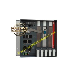
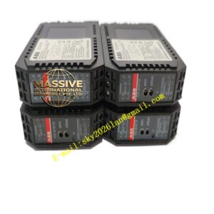
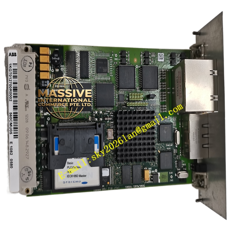
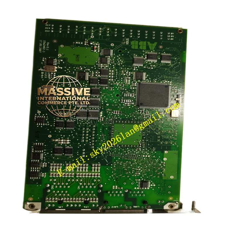
ABB 560CMU05
Technical Specifications:
- Processor: High-speed 32-bit microcontroller for rapid fault detection and logic execution.
- Communication Protocols: Supports IEC 61850 (GOOSE/Sampled Values), Modbus RTU/TCP, DNP3.0, PROFIBUS DP, and PROFINET.
- I/O Capacity: Up to 16 configurable digital inputs, 8 SPDT relay outputs, 4-8 analog inputs (4-20 mA), and 2 analog outputs.
- Power Supply: Universal power input supporting 24-250 VDC or 100-240 VAC/VDC.
- Display: Backlit graphical LCD with a 5-key navigation pad for local operation.
Functional Features:
- Comprehensive Motor Protection: Includes thermal overload (49), phase/ground overcurrent (50/51, 50N/51N), stall protection (51LR), under/over voltage (27/59), and negative sequence protection (46).
- Advanced Measurement: True RMS measurement of voltage, current, active/reactive power, power factor, frequency, and harmonics up to the 15th order.
- Automation Logic: Features programmable logic (ABB Logic) for complex interlocking, auto-start sequencing, and event sequencing (SOE) with 1ms resolution.
- Cybersecurity: Implements role-based access control, secure boot, and encrypted logging compliant with IEC 62351 and IEEE 1686 standards.
Application Scenarios:
- Protection and control of pumps, compressors, fans, and conveyors in oil and gas refineries.
- Motor management in mining operations, water/wastewater treatment plants, and power generation facilities.
- Integration into digital substations and smart grid environments via IEC 61850.
- Centralized monitoring in modern Motor Control Centers (MCCs).
Performance Parameters:
- Operating Temperature: Wide operating range from -20°C to +70°C without derating.
- Storage Temperature: Rated from -40°C to +85°C for harsh warehouse environments.
- Humidity Tolerance: Operates reliably in 5% to 95% relative humidity (non-condensing).
- Certifications: Compliant with IEC 60255, IEEE C37.90, UL 508, CSA C22.2, and ATEX for hazardous areas.
Material Composition & Structural Characteristics:
- Form Factor: Compact module designed for half 19-inch rack mounting or DIN rail installation (with adapter).
- Enclosure: Robust industrial housing providing high immunity to electromagnetic interference (EMC).
- Terminals: Pluggable, spring-loaded, or screw-type terminal blocks for secure field wiring.
- Weight & Dimensions: Lightweight industrial design (approx. 0.6 kg) with compact footprint (120 x 90 x 60 mm).
Working Principle:
The 560CMU05 continuously samples analog current and voltage signals via internal transducers. The 32-bit processor calculates real-time electrical parameters and compares them against user-configured protection curves and logic states. If a fault condition is detected, the unit executes pre-programmed logic to trip specific output relays, isolating the motor. Simultaneously, it packages operational data and event logs for transmission to the SCADA or DCS system via its diverse communication interfaces.
Installation Requirements:
- CT Wiring: Use shielded cables for Current Transformer (CT) connections and ground the shield at the CMU end only to prevent noise.
- Communication: Properly terminate PROFIBUS or RS-485 networks to prevent signal reflections; use Ethernet for IEC 61850 networks.
- Power: Ensure the universal power supply is correctly configured (AC vs. DC) before applying power.
- Configuration: Use ABB’s dedicated configuration software to set motor nameplate data, protection curves, and communication parameters before commissioning.
Usage Precautions:
- Motor Data Accuracy: Incorrect motor nameplate data or CT ratio configuration will lead to false tripping or failure to protect; verify all parameters twice.
- Relay Outputs: Do not switch inductive loads directly from the relay outputs without external interposing relays or suppression circuits.
- Firmware Updates: Always back up the current configuration file before performing any firmware upgrades.
- ESD Safety: Handle the module with standard Electrostatic Discharge (ESD) precautions during installation and maintenance.