Description
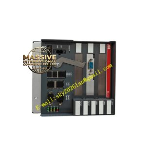
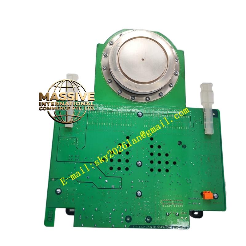
ABB 5SHX1960L0006 3BHB016120R0002 3BHE019719R0101 GVC736BE101
Technical Specifications:
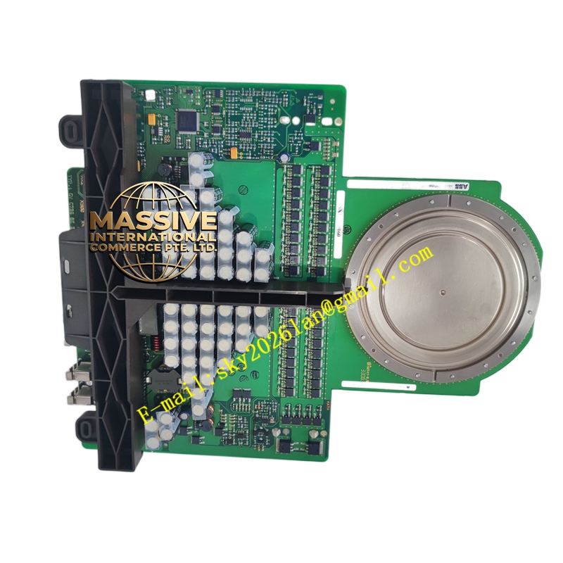
- IGCT Module: 5SHX1960L0006 (RC-IGCT, 91mm package).
- Gate Unit: GVC736BE101 (Integrated gate driver and power supply).
- Ordering Codes: 3BHB016120R0002 (Assembly), 3BHE019719R0101 (Component/ Spare).
- Control Interface: Fiber optic for trigger and status feedback.
- Power Input: 24 VDC for gate unit operation.
Functional Features:
- Matched Pairing: Factory-tested combination of IGCT and gate drive for guaranteed performance.
- Reverse Conduction: Integrated anti-parallel diode functionality within the IGCT chip.
- Status Feedback: Gate unit provides optical feedback for turn-on and turn-off verification.
- Compact Integration: Reduces assembly time and potential wiring errors in the converter stack.
Application Scenarios:
- Replacement kits for ABB medium-voltage drives (e.g., ACS 1000, ACS 6000).
- Upgrades for existing GTO-based converters.
- Custom high-power converter builds.
- Marine and offshore power systems.
Performance Parameters:
- Gate Pulse Energy: Optimized for minimal turn-on loss and safe turn-off.
- Propagation Delay: Precisely matched delay times for parallel operation.
- Isolation Voltage: High optical isolation between control and power circuits.
- MTBF: High Mean Time Between Failures for continuous industrial operation.
Material Composition & Structural Characteristics:
- Assembly Hardware: Precision-machined clamping frames and insulating sleeves.
- Gate Unit PCB: Multi-layer board with high-voltage isolation barriers.
- Optical Couplers: High-speed, high-reliability fiber optic transceivers.
- Thermal Pads: High-conductivity interface materials for heat transfer.
Working Principle:
The gate unit receives low-power optical commands from the system controller. It generates the high-peak-current pulses required to turn on the IGCT and the sustained reverse current to turn it off. The RC-IGCT handles both forward conduction and reverse freewheeling current, simplifying the converter topology.
Installation Requirements:
- Stack Assembly: Follow the exact stack-up sequence and pressure specifications.
- Fiber Routing: Route fibers away from hot surfaces and sharp edges.
- Power Connection: Connect 24VDC to the gate unit with proper polarity.
- Verification: Perform a low-voltage gate pulse test before energizing the main DC bus.
Usage Precautions:
- Kit Integrity: Do not mix components from different assembly kits.
- Optical Cleaning: Clean fiber ends with lint-free wipes and isopropyl alcohol.
- Power Sequencing: Ensure 24V gate power is stable before applying main voltage.
- Fault Response: Investigate and resolve any gate faults before attempting a reset.