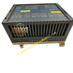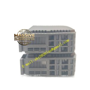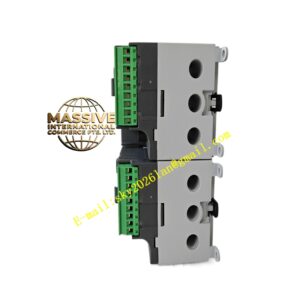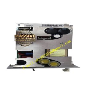
Description
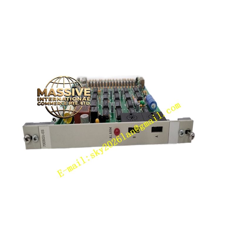
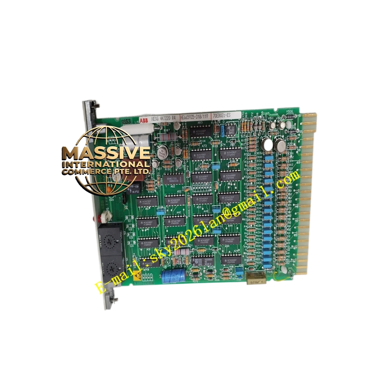
ABB 70EB02C-ES
Technical Specifications
| Parameter | Value |
|---|---|
| Input Channels | 16 digital contact inputs |
| Rated Voltage | 24V DC |
| Input Current | 2mA per channel |
| Response Time | 0.5 seconds |
| Processing Speed | 0.5 μs |
| User Program Capacity | 8000 steps (24K steps secure download) |
| I/O Points | 18 inputs / 14 outputs (system capacity reference) |
| Internal Relay Points (M) | 8000 points |
| Step Points (S) | 1024 points |
| Timer Points (T) | 620 points |
| Counter Points (C) | 635 points |
| Weight | 0.4 kg |
| Dimensions | 2″ × 6″ × 8″ (5.1 cm × 15.2 cm × 20.3 cm) |
Functional Features
- 16-Channel Digital Input: High-density 16-channel design for efficient binary signal acquisition from multiple field devices.
- Fast Response: 0.5-second response time ensures timely detection of status changes in monitored equipment.
- High-Speed Processing: 0.5 μs processing capability supports rapid scan cycles for time-critical applications.
- Large Program Capacity: 8000-step user program capacity accommodates complex control logic and sequencing.
- Comprehensive Internal Resources: Extensive internal relay, step, timer, and counter resources support sophisticated control algorithms.
- LED Status Indication: Front panel LEDs provide visual indication of input channel states for quick diagnostics.
Application Scenarios
- Motor Status Monitoring: Acquisition of motor starter contactor auxiliary contacts, overload relay status, and circuit breaker positions.
- Valve Position Indication: Monitoring of limit switch signals from motorized valves and dampers.
- Safety Interlock Systems: Collection of safety gate, emergency stop, and guard switch contact signals.
- Conveyor Systems: Detection of product presence, jam conditions, and conveyor operational status.
- Tank Level Switches: Interface with high-level, low-level, and alarm float switches.
Installation Requirements
- Install in Procontrol P13 system rack with proper grounding.
- Use appropriately rated cables for 24V DC signal wiring.
- Maintain separation between high-voltage power cables and low-voltage signal cables.
- Verify input voltage polarity before energizing to prevent damage.
Operating Precautions
- Ensure contact bounce filtering is configured for mechanical switch inputs.
- Monitor input channel LEDs for fault identification during commissioning and operation.
- Do not exceed maximum input voltage ratings to prevent module damage.
- Perform periodic inspection of terminal connections for looseness or corrosion.