Description
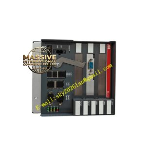
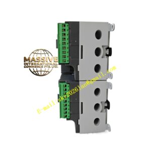
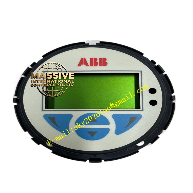
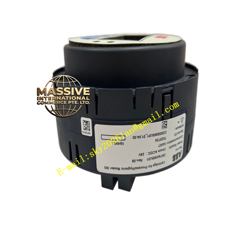
ABB D674A905U01
- Technical Specifications:
- Supply Voltage: 24 V DC (±15 %), typical consumption <100 mA
- Safety Inputs: 2 × single-channel or dual-channel (antivalence check), accepts N/C E-Stop or guard switch contacts
- Input Type: Wetting voltage provided; max input impedance per spec
- Safety Outputs: 2 × forcibly guided N/O (normally open) contacts, rated 6 A @ 250 V AC (resistive)
- Auxiliary Output: 1 × N/C or N/O (non-safety) for status signaling
- Reset Mode: Manual reset (via reset button / contact) or automatic (selectable by wiring)
- Response Time: <30 ms (typical <15 ms) from input closure to safe output pick-up
- Start-Up / Cross-Fault Detection: Monitors input wiring for cross-short between channels
- LEDs: Power (green), Safety OK (green), Fault (red), Input status
- Mounting: 35 mm DIN rail (EN 60715); width typically 22.5 mm
- Operating Temp.: –20 °C to +60 °C
- Standards: EN ISO 13849-1PL e, Cat. 4; IEC 61508SIL 3 (as safety relay function)
- Functional Features:
- Dual-channel antivalence check detects short across input wires
- External Device Monitoring (EDM) — verifies downstream contactor feedback
- Forcibly guided contacts guarantee N/C contact opens when N/O closes (and vice versa)
- Manual reset prevents unexpected restart after fault clearance or power recovery
- Compact design saves panel space vs. full safety PLC
- Application Scenarios:
- Emergency stop circuit for packaging machines, presses, conveyors
- Interlocked guard door on robot cells — prevents opening while hazard present
- Light curtain / safety scanner muting supervision (basic)
- Woodworking / metalworking machinery safety compliance
- Material & Structure:
- Housing: Gray/blue flame-retardant polyamide (PA66), width 22.5 mm
- Terminals: Cage-clamp or screw, tin-plated brass
- Internal: Redundant microprocessor + watchdog with self-test each cycle
- Working Principle:
On power-up the module performs internal self-tests. If safety inputs (E-Stop contacts) are closed (normal state — N/C contacts wired), and no cross-fault is detected, a manual or auto reset pulse causes the internal relay to pick, closing the safety N/O contacts and enabling the machine control circuit. Opening an input (E-Stop pressed / guard opened) causes immediate drop-out of safety relay within the certified response time. Faults (short across inputs, internal watchdog failure) lock the outputs OFF until the fault is cleared and a reset is performed.
- Installation Requirements:
- Mount on 35 mm DIN rail in control panel
- Wire N/C E-Stop / safety gate contacts to Input A & Input B terminals (dual-channel) or jumper for single-channel (reduced category)
- Connect 24 V DC supply to A1/A2 observing polarity
- Wire safety N/O contacts in series with machine enable circuit / contactor coil via safety-rated forced-guided aux contacts (EDM feedback optional)
- Connect reset button (N/C contact to reset terminal +24 V) for manual reset mode
- Precautions:
- Do NOT bypass safety inputs — defeats safety function and violates machinery directives
- Always use forcibly guided (positive-guided) contactors/relays in the downstream enable circuit; verify with EDM if required by risk assessment
- Test the E-Stop function after installation — verify safety outputs drop out and fault LED appears
- Periodic functional test per machine safety plan (typically annually or per LOTO procedure) is mandatory to confirm correct operation