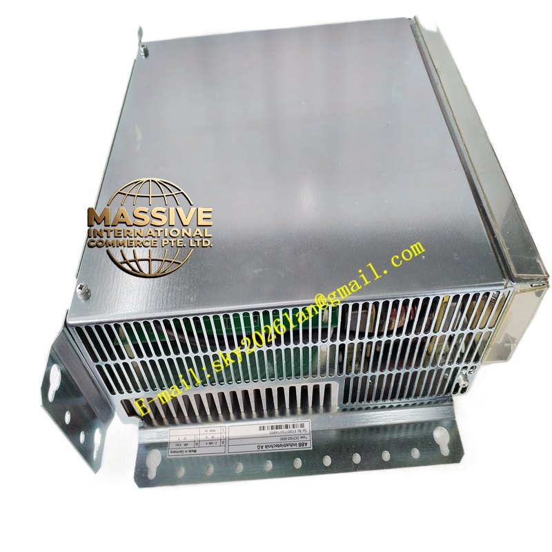
Description
ABB DC541-CM 1SAP270000R0001
Technical Specifications:
- System Compatibility: ABB AC500 PLC Series.
- Communication Protocols: Supports PROFIBUS DP, CANopen, or Modbus RTU (depending on specific variant).
- Data Transfer Rate: High-speed baud rates up to 12 Mbps.
- Node Capacity: Supports extensive network topologies with multiple slave/master nodes.
Functional Features:
- Seamless Integration: Plug-and-play compatibility with AC500 CPU base units.
- Protocol Conversion: Translates internal PLC bus data into standard industrial fieldbus protocols.
- Diagnostic Capabilities: Real-time monitoring of bus status, error logging, and LED indication for network health.
- Hot-Swap Support: Allows for module replacement without powering down the entire PLC rack (system dependent).
Application Scenarios:
- Distributed automation in manufacturing assembly lines.
- Machine-level control and networking.
- Integration of third-party devices into ABB control systems.
Performance Parameters:
- Latency: Ultra-low communication latency for deterministic control.
- Isolation: Galvanic isolation between the PLC backplane and the fieldbus network.
- Reliability: High MTBF designed for 24/7 industrial operation.
Material Composition & Structural Characteristics:
- Form Factor: Compact, front-access module matching the AC500 series aesthetic.
- Connectors: Standard DB9 or terminal block interfaces for fieldbus cabling.
- Indicators: Multi-color LEDs for Power, Transmit, Receive, and Bus Fault status.
Working Principle:
The module interfaces directly with the AC500 CPU via the backplane. It buffers outgoing control data, formats it according to the selected fieldbus protocol, and transmits it serially. Incoming data from field devices is received, validated, and mapped to the PLC’s internal memory space for processing.
Installation Requirements:
- Slot Assignment: Install in the designated communication slot adjacent to the CPU.
- Termination: Apply proper termination resistors at both ends of the fieldbus network.
- Addressing: Configure the unique node address using hardware DIP switches or software.
Usage Precautions:
- Cable Routing: Keep fieldbus cables away from high-voltage motor cables to prevent EMI.
- Firmware: Ensure the module firmware is compatible with the CPU and configuration software.
- Grounding: Properly shield and ground the communication cable to prevent ground loops.