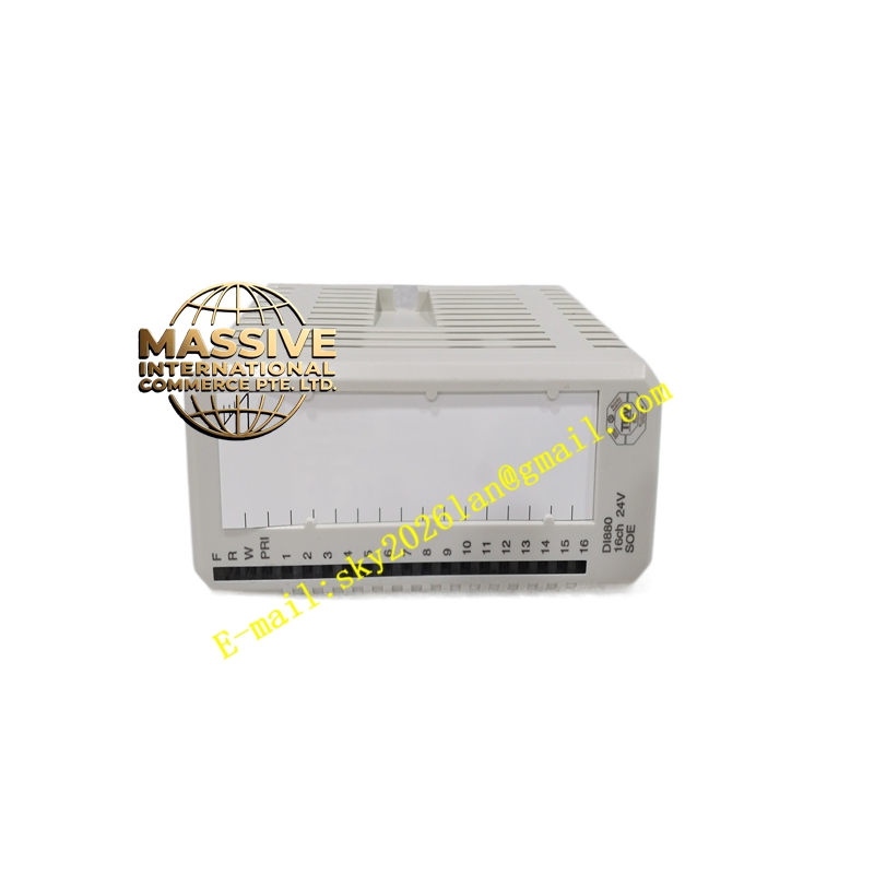
Description
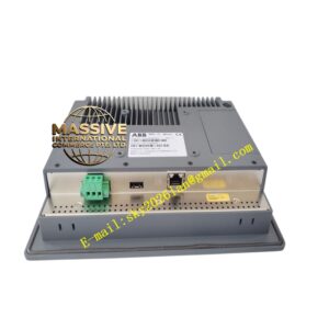
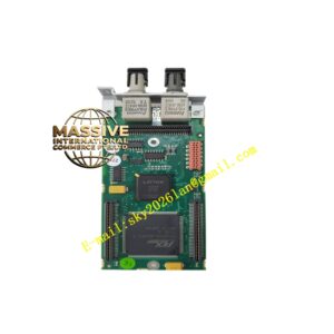
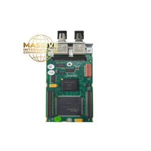
ABB DO524 A3
- Technical Specifications:
- Output Channels: 32 (transistor, NPN high-side sourcing)
- Output Voltage: 24 V DC (20.4–28.8 V DC rated)
- Output Current: 0.5 A per channel continuous; total module max ≈8 A (derate per group / ambient)
- Output Type: Current sourcing (PNP), short-circuit proof, overload protected, auto-recover
- Voltage Drop (ON): <0.8 V at rated current
- Turn-on/off Time: <1 ms
- Isolation: Galvanic isolation between logic side and field side (test 500 V AC)
- Process Supply (UP): 24 V DC via terminals (fused max 10 A fast)
- Current Consumption from CPU: ≈2 mA + load current from UP
- Power Dissipation: Max ≈6 W (unloaded); higher with load
- Indicators: 1 yellow LED per channel (ON = output active) + module status LED
- Mounting: 35 mm DIN rail (horizontal or vertical with derating — at +40 °C vertical, reduce load to 50 %)
- Dimensions: ≈62 × 76 × 68 mm (W × H × D); weight ≈0.1 kg
- Protection: IP20, reverse polarity protection on process supply, temporary overvoltage ≤30 V DC
- Max Field Cable Length: 600 m unshielded / 1000 m shielded (per ABB recommendation)
- Certifications: CE, UL, cUL, RoHS
- Functional Features:
- 32 high-density outputs in one slim module — minimizes panel space
- Individual channel short-circuit protection with automatic reset after fault clears
- Diagnostic LEDs for rapid troubleshooting
- Reverse polarity and overvoltage protection on process supply terminals
- Compatible with AC500 CPUs (PM5xx) and CS31 / Profibus / Ethernet remote I/O heads (S500)
- Application Scenarios:
- Packaging / bottling lines — solenoid valve and indicator beacon control
- Conveyor system divert gate / stopper actuation
- Building automation — lighting, damper, fan contactor control
- Machine tools — coolant pump start, indicator lamps, small DC loads
- Material & Structure:
- Housing: Flame-retardant polyamide (PA66) gray, DIN-rail clip integrated
- Terminals: Cage-clamp / spring-pressure, tin-plated brass
- PCB: FR4 with solder mask and conformal coat option
- Working Principle:
The module receives output image bits from the AC500 CPU via the local bus or fieldbus interface. Each bit controls a protected P-channel MOSFET high-side driver which connects the output terminal to the UP (+24 V) process supply when ON, and disconnects it when OFF. Short-circuit is detected by monitoring MOSFET voltage drop; excessive current forces the channel into limitation and latches a fault until the condition is removed and the output is re-enabled by the CPU.
- Installation Requirements:
- Snap onto 35 mm DIN rail in panel; leave ≥10 mm above/below for ventilation
- Wire +24 V DC process supply to UP terminals, 0 V to ZP terminals observing polarity
- Connect field load between output terminal and 0 V return
- Torque terminals to manufacturer spec (typically 0.5–0.6 N·m)
- In vertical mounting above +40 °C ambient, apply load derating (max 50 % of rated per channel)
- Precautions:
- Total continuous current must not exceed module/wiring fuse rating — distribute load evenly across channels
- Do NOT connect AC voltage to outputs — DC-only, will be damaged
- For inductive AC loads (contactors, relays), use interposing DC relay with flyback diode or snubber on coil
- Ensure process supply fuse ≤10 A fast-blow — larger fuses compromise module short-circuit protection