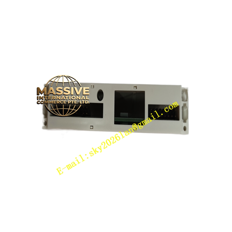
Description
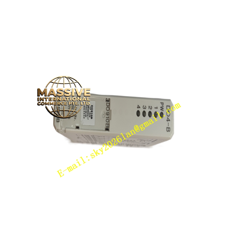
ABB DO910
Technical Specifications
| Parameter | Value / Description |
|---|---|
| Signal Type | 24 V DC transistor, high-side (current sourcing / PNP) |
| Number of Channels | 8 (S800 DO910 typical) — 4 (S900 DO910S Ex i variant) |
| Output Voltage Range | 12–32 V DC (nominal 24 V DC process supply UP) |
| Max Continuous Current | 0.5 A per channel (S800); S900 Ex i version limited to IS energy constraints (typ. 40 mA Ex i) |
| Total Module Load | ≤4 A (S800, 8-ch version, group thermal limit applies) |
| Output Type | Non-latching, high-side MOSFET with free-wheeling diode for inductive load suppression |
| Short-Circuit Protection | Current-limited; auto-recovery after fault clears (S800 version) |
| Isolation | Group-wise isolated from ModuleBus (500 V a.c. dielectric test, 50 V rated insulation); channel-to-channel NOT isolated within group |
| Process Voltage Supervision | One supervision input per group — module warning/fault if UP absent |
| On-State Voltage Drop | <0.5 V @ 0.5 A typical |
| Turn-On / Turn-Off Delay | <50 µs / <200 µs |
| Leakage Current (OFF) | <0.5 mA |
| Max Field Cable Length | 600 m shielded (S800); S900 Ex i follows IS cable parameter limits |
| Inductive Load Handling | Internal free-wheeling diode; for large inductance verify energy within spec |
| Diagnostics | Per-channel yellow LED (ON = output active); module Run / Fault / Warning / OSP LEDs |
| OSP (Output Set to Predefined) | Configurable — Off / Last State / On upon comm loss or module fault (S800 version) |
| Power Dissipation | Typ. 1.8–2.1 W (fully loaded 8-ch version) |
| ModuleBus Current Draw | +5 V: typ. 80 mA; +24 V ext. (process): drawn from external UP terminal, not from backplane |
| Operating Temperature | 0 °C to +55 °C (for vertical mount in compact MTU max +40 °C); storage –40 °C to +70 °C |
| Humidity | 5–95 % RH, non-condensing |
| Enclosure Protection | IP20 (module in cabinet); S900 front cover IP54/65 per variant |
| Mounting | 35 mm DIN rail via Terminal Unit (TU810 / TU812 / TU814 / TU830 / TU833 / TU842 / TU843 / TU852) |
| | 45 mm (W) × 119 mm (H) × 102 mm (D); weight ≈0.18 kg |
| Certifications | CE, UL 61010-1, cULus, ATEX / IECEx Zone 2 (); ATEX / IECEx Zone 1 with S900 IS barrier (DO910S) |
| Conformal Coating | G3 per ISA-S71.04 standard on I/O modules |
Functional Features
- High-Side Sourcing Outputs: Directly switches 24 V DC to field loads — simplifies wiring for PNP (sourcing) sensors/valves common in European practice.
- Short-Circuit & Over-Temp Protection: Each channel current-limited; module survives sustained short to ground or 30 V DC; auto-recovers when fault removed.
- Process Voltage Supervision: Detects loss of 24 V DC field supply (UP) and reports diagnostic to controller — prevents silent output failure.
- OSP (Safe State on Error): Configurable output behavior on communication loss, module fault, or watchdog timeout — essential for fail-safe process designs.
- Hot-Swap Capability: Module can be inserted/removed with MTU powered when station configured for hot-swap — minimizes downtime during maintenance.
- Status LEDs: Individual channel + module-level Run / Fault / Warning / OSP for rapid local troubleshooting without laptop.
- Inductive Load Suppression: Built-in free-wheeling path protects MOSFET from back-EMF of solenoid/relay coils.
- (S900 DO910S only):Intrinsically safe Ex i outputs with channel-to-channel isolation, line fault detection (open/short), suitable for Zone 1/Division 1 installation with approved IS barrier.
Application Scenarios
- Process Plant Final Element Control: 24 V DC solenoid valves for open/close or modulating (on/off) service — cooling water dump valve, steam header vent, sample tap actuator.
- Auxiliary Equipment Control: Start command to 24 V DC interposing relay for motor starter coil, lube oil pump contactor, or fan starter.
- Visual Annunciation: 24 V DC stack lights, beacon flashers, local alarm horns in control rooms or field kiosks.
- Packaging / Converting Machinery: Clamp/unclamp solenoid, part-present reject gate actuator controlled via AC500 + remote I/O.
- ( DO910S):Driving intrinsically safe solenoid valves on shutdown skids or analyzers located in classified (Zone 1/Zone 0) areas — fire & gas, ESD final elements in hazardous zones.
Material Composition & Structural Characteristics
- Housing: Flame-retardant polycarbonate/ABS blend (gray), UL 94 V-0 rated, with transparent polycarbonate status window.
- PCB: Industrial-grade FR4 with G3 conformal coating for resistance to corrosive atmospheres (H₂S, SO₂, NaCl).
- Terminals: Field wiring terminates on Terminal Unit (TU) — screw or spring-cage type available on TU; module itself engages TU via gold-plated backplane edge connector.
- Keying / Coding: Physical key on module bottom engages coded slots on MTU — prevents insertion of wrong module type into incompatible MTU.
- Heat Dissipation: Internal copper plane spreads heat from MOSFETs; adequate cabinet ventilation required especially when multiple outputs heavily loaded.
Working Principle
The DO910 receives a digital output image bit from the controller via the ModuleBus cyclic data exchange. An opto-isolator triggers a P-channel MOSFET high-side driver which connects the output terminal to the externally supplied process voltage (UP = +24 V DC). When the image bit is ‘1’, the MOSFET turns ON, supplying 24 V DC to the field load; when ‘0’, it turns OFF. Each channel monitors its own current — if current exceeds the short-circuit limit, the driver is throttled or switched off and a diagnostic flag is set. On communication loss or internal fault, outputs assume the pre-configured OSP state (OFF / ON / Last). Process voltage on the UP terminal is continuously monitored; disappearance triggers a Warning diagnostic.
Installation Requirements
- Mount the Terminal Unit (TU): Secure the appropriate MTU (e.g., TU810, TU830) on a 35 mm DIN rail inside the cabinet; ensure proper earth bonding of the rail/chassis.
- Insert Module: Align DO910 with MTU guide rails, press in until it seats and the retaining screw can be engaged. Verify key-code matches MTU setting (typically code AA for 24 V DC DO modules).
- Wire Process Supply: Connect +24 V DC (UP) to the process voltage terminal on TU, and 0 V (ZP) to the common return terminal. Fuse the UP supply appropriately (typically 10 A fast-blow max per TU common terminal rating).
- Wire Field Devices: Connect load between the output terminal (O0…O7) and 0 V return (ZP). For sourcing (PNP) outputs, the load completes the circuit to 0 V.
- Shield & Ground: Use shielded twisted-pair for long runs; connect shield to cabinet earth at one end only (preferably cabinet end).
- Configure in Engineering Software: In Control Builder / Freelance Engineering Workbench, add DO910 to I/O configuration, set OSP behavior, process voltage supervision enable/disable, and download to controller.
- Power-Up & Test: Energize 24 V DC supply, verify Run LED green, test each output via force function — confirm field device operates and channel LED illuminates.