Description
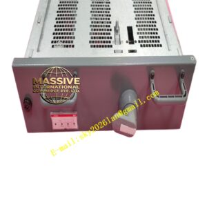
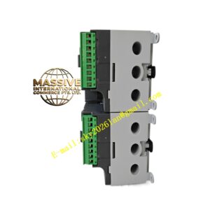
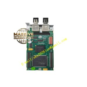
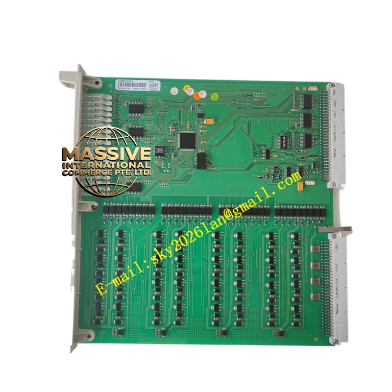
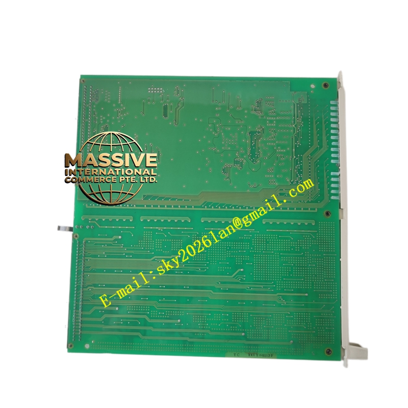
ABB DSDO115K12 3BSE019933R1
Technical Specifications:
- Output Type: Discrete digital outputs (sourcing or sinking).
- Voltage Rating: Compatible with standard industrial control voltages (e.g., 24V DC).
- Current Rating: Rated for continuous industrial load currents.
- Channel Count: Multiple independent output channels per module.
- Isolation: Galvanic isolation between outputs and internal logic.
Functional Features:
- Reliable Switching: Solid-state or relay outputs designed for high-cycle industrial applications.
- Diagnostic Feedback: Reports output status, short circuits, and open loads to the controller.
- Fail-Safe Operation: Configurable safe state upon loss of communication or power.
- High-Speed Switching: Fast response times for precise timing control.
Application Scenarios:
- Solenoid valve control in pneumatic and hydraulic systems.
- Motor starter and contactor coil control.
- Alarm horn, beacon, and indicator lamp control.
- Discrete interlocking and safety permissive signals.
Performance Parameters:
- Switching Speed: Millisecond-level response time.
- Load Capacity: Sufficient current drive for standard industrial loads.
- Electrical Life: High-cycle rated for long-term reliability.
- Protection: Built-in overcurrent and short-circuit protection.
Material Composition & Structural Characteristics:
- Output Stage: High-reliability solid-state switches or electromechanical relays.
- PCB: Heavy copper traces for current handling and thermal management.
- Terminals: Secure screw or spring-clamp terminals for field wiring.
- Indicators: Per-channel LEDs for visual status verification.
Working Principle:
The module receives digital ON/OFF commands from the controller. The output driver circuitry energizes or de-energizes the output stage, switching the external load. Diagnostic circuits continuously monitor the output state and load current, reporting any faults (e.g., short circuit, wire break) back to the controller for alarm handling.
Installation Requirements:
- Load Wiring: Use appropriately sized wire for the connected load current.
- Inductive Loads: Install flyback diodes or snubbers across inductive loads to protect output contacts.
- Power Supply: Ensure the field power supply has adequate capacity for all connected loads.
- Configuration: Set output type, fail-safe mode, and diagnostic parameters in software.
Usage Precautions:
- Overcurrent Protection: Never exceed the rated output current; use external interposing relays for high-power loads.
- Short Circuit: Avoid short-circuiting output terminals; verify wiring before energizing.
- Heat Dissipation: Ensure adequate ventilation when driving continuous high-current loads.
- Maintenance: Periodically inspect output connections and verify switching operation.