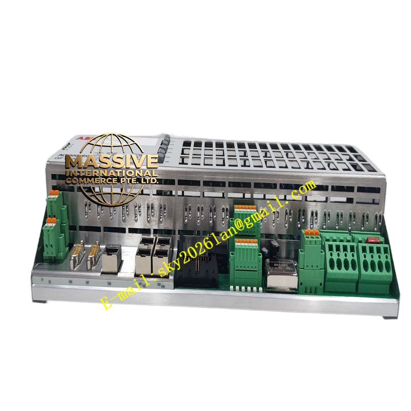
Description
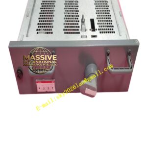
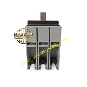
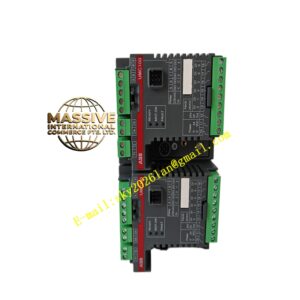
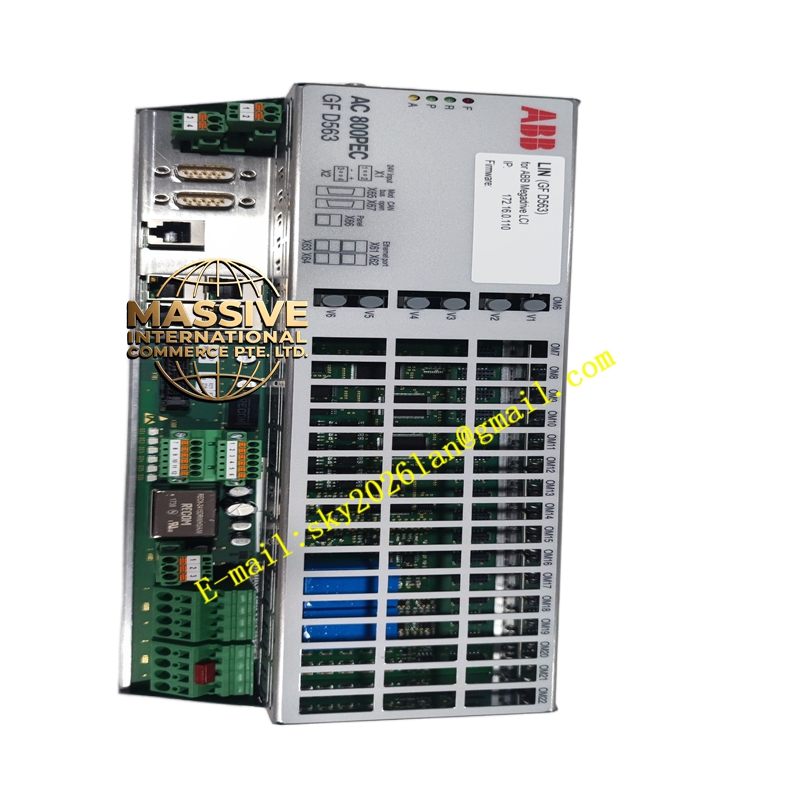
ABB GFD563A101
- Technical Specifications:
- Processor: 32-bit dual-core RISC (typical 800 MHz class)
- Regulation Cycle Time: Current loop 100 µs; Voltage / PSS loop 1 ms
- Input Signals: Generator terminal voltage (PT/VT secondary), stator current (CT secondary), field current/voltage, speed signal
- Output Signals: PWM firing pulses to thyristor bridge, limiting/Alarm contacts
- Communication: Ethernet 10/100 Mbps (Modbus TCP, IEC 61850-8-1 MMS/GOOSE optional), Profibus DP-V1, serial (RS-232/485) for local HMI
- Fiber Optic I/O Link: 100 Mbps to AC 800PEC I/O modules (gate pulse, feedback)
- Auxiliary Supply: 24 V DC (18–32 V DC), typ. 120–150 W
- Isolation: Control side / power side ≥2.5 kV (optical fiber / isolated I/O)
- Operating Temp.: –20 °C to +60 °C
- Mounting: 19″ rack / cabinet panel or DIN-rail sub-frame per AC 800PEC enclosure
- Dimensions (approx.): 200 × 150 × 100 mm (module only), larger in enclosed chassis
- Diagnostics: Run, Com, Sync, Fault LEDs; internal event log with 1 ms time stamp
- Functional Features:
- UEL (Under-Excitation Limiter), OEL (Over-Excitation Limiter), V/Hz limiter built-in
- PSS2A / PSS4B (Power System Stabilizer) support for grid stability
- Low-Voltage Ride-Through (LVRT) per IEC 61400-21/ IEEE 421.5
- Manual / Auto transfer, tracking between voltage regulator and manual field current control
- Online parameter modification and trend recording via Control Builder or excitation HMI
- Application Scenarios:
- Unitrol 5000 / Unitrol 1040 static excitation systems for generators 1 MW–1000 MW+
- Retrofit of legacy excitation cubicles (BBC / ABB older AVRs)
- Combined-cycle / cogeneration plant generator voltage regulation
- Hydro generator excitation with PSS for grid stability
- Material & Structure:
- Housing: Aluminum alloy or sheet-steel with vent slots; PCB with conformal coat
- Connectors: D-sub for sync/feedback, RJ45 or fiber ST for comms, screw terminals for 24 V DC / contacts
- Heat dissipation: Conduction via chassis or small internal fan in enclosed version
- Working Principle:
The module continuously samples generator PT voltage and CT current, computes terminal voltage error vs. setpoint, passes it through PSS and limiter blocks, then through PI voltage regulator → current reference → thyristor firing angle calculation. Firing pulses are sent optically to the thyristor bridge gate units. If excitation is lost or a fault is detected, the module triggers field suppression (via field breaker / discharge resistor contact) and raises an alarm.
- Installation Requirements:
- Mount in excitation cubicle with adequate ventilation / cooling fan
- Connect 24 V DC auxiliary supply (separate from thyristor power)
- Connect PT/VT and CT secondary wiring observing polarity and burden limits
- Connect fiber optic link to gate pulse unit; verify link status LED
- Commission via ABB excitation engineering tool — perform OLF (Open Loop Test) before closing field breaker
- Precautions:
- High-voltage PT/CT secondaries must be fused and correctly grounded per local code
- Never energize thyristor bridge firing circuits before verifying synchronization signal polarity
- Perform periodic functional test of limiters (UEL/OEL) per maintenance schedule
- Keep firmware version compatible with rest of AC 800PEC I/O and engineering software