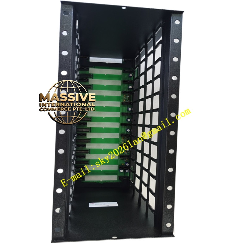
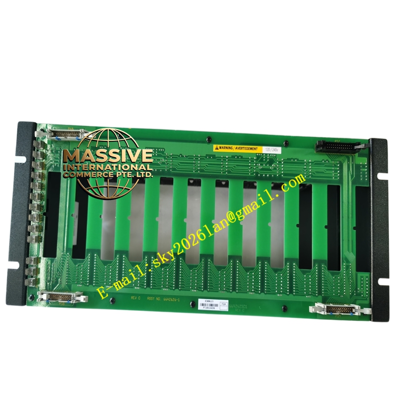
Description
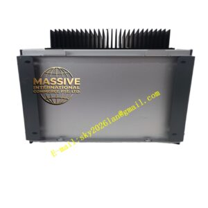
ABB IEMMU21
- Technical Specifications:
- Slot Capacity: 10 module slots (positions 1–10); slot 1 often reserved for controller/communication module (e.g., INNIS21 / INICT13)
- Backplane Bus: Control Way (C.W.) — 50 Mbps synchronous serial bus; also C.B. (Communication Bus) for legacy
- Power Inputs: Dual redundant +5 V DC (logic, typ. 5 A–15 A depending on load) and +24 V DC (aux, for I/O excitation); screw terminals
- Maximum Module Load: Determined by sum of all inserted modules (typical full rack ~10–20 A @ 5 V depending on mix)
- Power Dissipation (empty): ~5 W; loaded per module spec
- Indicators: Power Good LED (green), Fault LED (red), Bus Active LED
- Physical: 19″ rack-mountable (sub-rack), approx. 483 mm (W) × 133 mm (H, 3U) × 280 mm (D); weight ~3.5 kg empty
- Operating Temp.: 0 °C to +60 °C
- Protection: IP20 (when installed in cabinet)
- Certifications: CE, UL, cUL, marine approvals (DNV, ABS, etc.)
- Functional Features:
- Supports redundant 5 V / 24 V DC power feeds with automatic switchover (diode-OR inside)
- C.W. bus termination resistors (switch/jumper selectable) for first/last rack in multi-rack chain
- Module keying / slot addressing via physical backplane — modules auto-enumerated by controller
- Compatible with INFI 90 / Harmony function processors (BRC-100, BRC-300, IMCP, etc.) and all standard I/O modules (IMASI, IMDSO, IMFEC…)
- Hot-swap capable — modules can be inserted/removed with rack powered (subject to system config)
- Application Scenarios:
- Central I/O rack in INFI 90 / Harmony DCS control cabinets
- Local or remote I/O cluster — connected via C.W. extender (INSEM01 / fiber optic link) to controller rack
- Retrofit / expansion of existing Bailey INFI 90 plants (power, refining, pulp & paper)
- Material & Structure:
- Chassis: Sheet steel, painted light gray (RAL 7035), with vent slots for convection cooling
- Backplane PCB: Multilayer controlled-impedance C.W. bus with gold-finger edge connectors (30-position per slot)
- Power Terminals: Tin-plated brass screw terminals (accept 0.5–4 mm² wire)
- Guide Rails: Aluminum or molded plastic for module alignment
- Working Principle:
The EMMU distributes regulated 5 V DC (logic) and 24 V DC (I/O excitation) from the plant power supply to each module via the backplane. The C.W. bus cyclically polls each addressed module for I/O data and downloads control outputs. The rack’s built-in termination resistors (when configured as first or last in a multi-rack C.W. chain) prevent signal reflections. Dual power inputs are diode-OR combined so loss of one supply does not interrupt operation.
- Installation Requirements:
- Mount in 19″ cabinet using 4 × M6 screws; leave ≥50 mm top/bottom clearance for airflow
- Connect +5 V DC (redundant A & B) to P5A/P5B terminals; connect +24 V DC to P24A/P24B; earth to PE terminal
- Insert modules starting from Slot 1 (leftmost = controller/comm module if used); verify key aligns
- Set C.W. termination jumpers — “TERM” on first and last rack in C.W. daisy-chain; “NORM” on intermediate racks
- Power up; verify Power Good LED; check module Run LEDs after system download
- Precautions:
- Do NOT mix +5 V logic and +24 V auxiliary wiring — reversed polarity or cross-connection damages modules
- Ensure total current draw of all modules < power supply rating + 20 % margin
- Before hot-swapping a module, confirm system is configured for hot-swap and rack power is stable
- Verify C.W. termination — missing or duplicate termination causes communication errors on C.W. bus