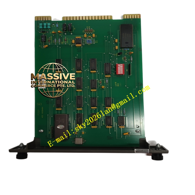
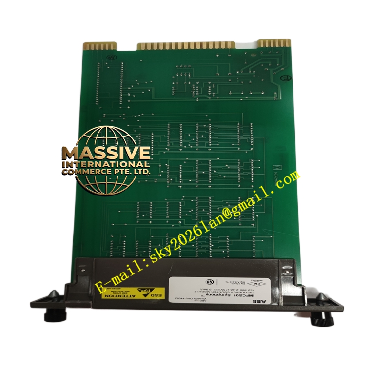
Description
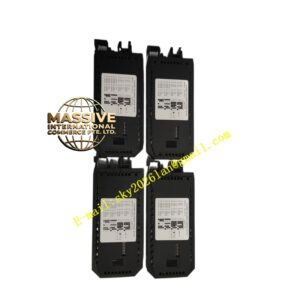
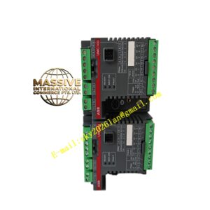
ABB IMFCS01
- Technical Specifications (typical):
- Input Channels: 1 or 2 independent channels (model-dependent; often 2 for redundant speed signals)
- Input Type: Magnetic pickup (passive, sine wave 50 mV–100 V pp) or proximity probe (active 8–24 V DC, TTL/HTL)
- Frequency Range: 0.1 Hz – 20 kHz (typical; corresponds to 6–120 000 rpm depending on gear teeth count)
- Teeth-per-Revolution (T.R.): Software-configurable (1–255)
- Measurement Period: Selectable (e.g., 100 ms, 500 ms, 1 s) — trade-off between update rate and low-speed resolution
- Accuracy: ±0.05 % of reading + 1 count
- Signal Conditioning: Built-in gain amp, Schmitt trigger, noise rejection filter
- Output (to Controller): Scaled speed value (rpm or Hz), alarm flags (overspeed, underspeed, sensor fail)
- Isolation: Input-to-backplane 500 V DC
- Module Power: 5 V DC from backplane (typ. 250 mA)
- Indicators: Run, Fault, Alarm LEDs; per-channel Activity LED (blinks with pulse train)
- Operating Temp.: 0 °C to +60 °C
- Functional Features:
- Dual-channel for redundant speed measurement (voted in controller)
- Configurable high/low speed alarm setpoints and deadband
- Sensor health monitoring (loss of signal, amplitude too low → sensor fail alarm)
- Smoothing / damping filter to reduce speed fluctuation reading
- Application Scenarios:
- Steam / gas turbine governor speed feedback (typically 60 teeth wheel + magnetic pickup → IMFCS01)
- Compressor shaft speed for anti-surge control
- Overspeed protection trip input (redundant FCS modules feeding separate trip logic)
- Centrifuge / rotating machine monitoring in process plants
- Material & Structure / Working Principle / Installation / Precautions:
- Mount in IEMMU21 rack; wire magnetic pickup shield twisted-pair to TA (Termination Assembly) for FCS; connect shield to ground at one end
- In config tool set T.R. (teeth per revolution) to match gear wheel; set measurement period appropriate for min expected speed (longer period = better low-speed resolution)
- Verify pickup gap (typically 0.25–1.0 mm for proximity probe; 0.5–1.5 mm for mag pickup) per probe manufacturer
- Precaution: Loss of speed signal can cause turbine trip — verify sensor integrity and gap during commissioning; test alarm setpoints
- For redundant speed inputs, use two separate IMFCS01modules or dual-channel version — never share sensor or wiring between safety channels without separation