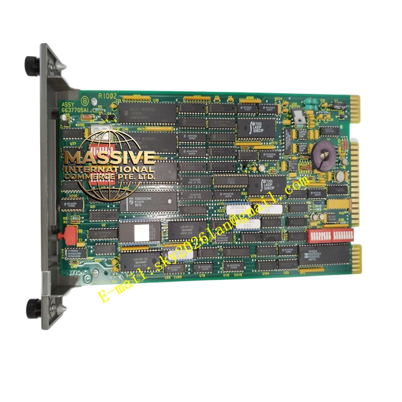
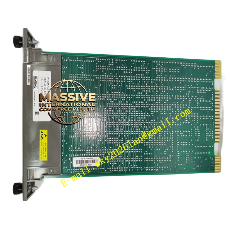
Description
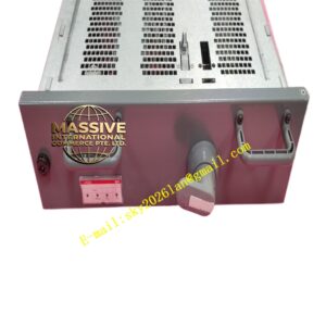
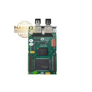
ABB IMRIO02
- Technical Specifications (typical):
- Function: C.W. bus regenerative repeater / remote I/O link interface
- Ports: 1 × C.W. IN (from controller rack), 1 × C.W. OUT (to next local rack or to remote link), sometimes a “Remote” port for fiber pair
- Max Electrical C.W. Distance: With repeaters (IMRIO02 chained) up to ~300 m per segment; total system length depends on number of repeaters (max 3–4 repeaters per C.W. chain typically)
- Fiber Support: When used with external fiber modems (or built-in on some RIO02 variants) — multimode up to 2 km, single-mode up to 15 km
- Data Rate: C.W. bus 50 Mbps (synchronous)
- Isolation: 500 V DC signal isolation between ports (on some versions)
- Power: 5 V DC + 24 V DC from backplane
- Indicators: Power, C.W. Active (local / remote), Link Status, Error LEDs
- Operating Temp.: 0 °C to +60 °C
- Mounting: Single slot in IEMMU21 (typically adjacent to INNIS21 in controller rack; remote I/O rack also has IMRIO02 as terminator/repeater)
- Functional Features:
- Signal re-timing and re-driving — eliminates degradation over long C.W. runs
- Supports multi-drop remote I/O — one controller can serve several remote I/O clusters (each with its own IEMMU21 + IMRIO02 as link terminator)
- Compatible with redundant C.W. (A/B bus) — two IMRIO02 modules per rack for A/B redundancy
- Diagnostic counters (CRC errors, re-transmissions) readable from controller
- Application Scenarios:
- Extending I/O to a remote pump house / turbine island 100–500 m from main control building
- Separating ground domains — fiber link via IMRIO02+ fiber modems eliminates ground loop between buildings
- Large plant with centralized INFI 90 controller and distributed I/O in several process areas
- Material & Structure / Working Principle / Installation / Precautions:
- In controller rack: insert next to INNIS21; connect C.W. OUT to remote link (copper via another as repeater, or to fiber modem pair)
- In remote I/O rack: insert ; connect C.W. IN from controller-side link; C.W. OUT to next local rack (if daisy-chained) or terminate with resistor if last
- Set C.W. termination — first and last node in C.W. chain have TERM jumper; itself does NOT replace terminator — the final rack’s EMMU still needs term resistor
- Precaution: Do NOT create C.W. loop (ring) — C.W. is a linear bus, not a ring — miswired ring causes bus hang. Verify correct port assignment (IN vs OUT). For fiber, clean connectors and verify link LED before system commissioning.