Description
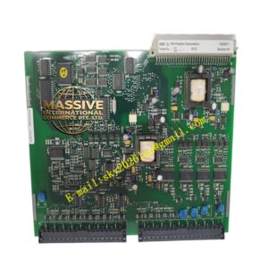
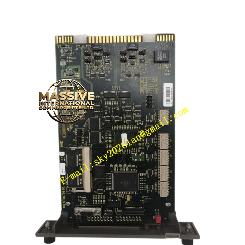
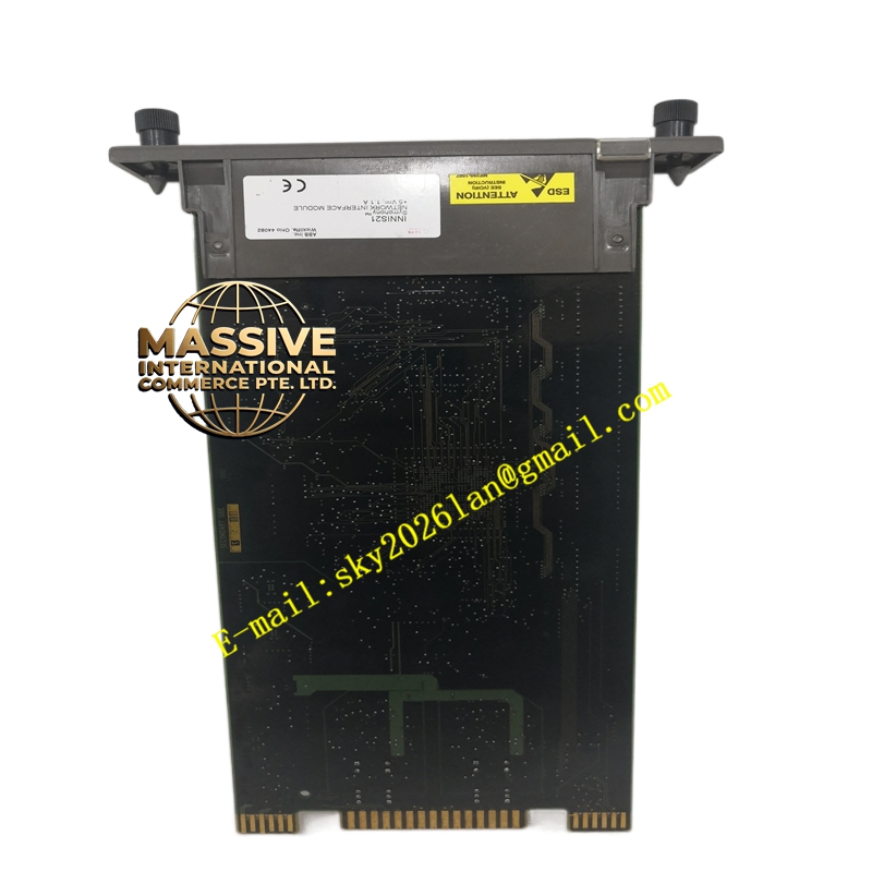
ABB INNIS21
- Technical Specifications:
- Network Type: Infi-Net(ABB proprietary — token-passing on redundant A/B rings)
- Physical Media: RG-62 A/U coaxial cable (BNC “T” connectors) or Shielded Twisted Pair (STP) — model suffix indicates media
- Data Rate: 10 Mbps (baseband)
- Node Address: Set via DIP switches on module (1–254; unique per node on network)
- Ports: 2 × BNC (A-ring IN/OUT) + 2 × BNC (B-ring IN/OUT) or STP RJ-style depending on version; also a “Local” port for C.W. connection to backplane
- Redundancy: Supports dual INNIS21 (A-net / B-net) — automatic switchover on ring failure
- Module Power: 5 V DC from backplane (typ. 400 mA); 24 V DC for some options
- Indicators: Power (green), Run (green), Error (red), Net A Active / Net B Active (green), Ring Terminator (if jumper set)
- Operating Temp.: 0 °C to +60 °C
- Compatibility: Works with BRC-100, BRC-300, IMCP01/02 controllers; pairs with INICT13 (Intelligent Communications Interface w/ co-processor for complex protocols) in some architectures
- Functional Features:
- Peer-to-peer data exchange — allows controller to read/write analog/digital blocks in other nodes (setpoint cascade, unit coordination)
- Broadcasts alarms/events to OIS (Operator Interface Station) and to gateway modules
- Time distribution — can act as time master or slave on Infi-Net (distributes NTP-like time to nodes)
- Built-in self-test and ring fault diagnostics (reports open-ring, duplicate node address, excessive retries)
- Application Scenarios:
- Every INFI 92 / Harmony controller rack — INNIS21 is the “network card” connecting it to plant Infi-Net
- Multi-unit plant — unit 1 controller talks to unit 2 controller via Infi-Net peer blocks
- Interface to OIS (operator consoles), INGSM08 (Modbus gateway), INIET800(migration bridge)
- Material & Structure / Working Principle / Installation / Precautions:
- Install INNIS21 in Slot 1 of IEMMU21 controller rack; ensure key matches
- Set node address DIP switches BEFORE inserting — address must be unique on Infi-Net; document all node addresses
- Connect coax cables: A-Ring IN from previous node (or terminator if first), A-Ring OUT to next node (or terminator if last); same for B-Ring
- If first or last node on a ring: install 93 Ω terminator (BNC terminator plug) on unused OUT port; set onboard TERM jumper to enable internal termination if design calls for it (usually external terminator plugs are used)
- Power up; verify Run LED green, Net A / Net B LEDs blink (traffic); confirm node appears in OIS / network diagnostics
- Precautions:
- NEVER insert/remove INNIS21 while rack is powered unless hot-swap confirmed configured — typically power down controller rack for initial installation
- Verify coax cable type (RG-62 A/U 93 Ω characteristic impedance) — using RG-59 (75 Ω) causes reflections and communication errors
- Both A-ring and B-ring MUST be properly terminated — missing terminator causes intermittent loss of redundancy or complete comm failure on that ring
- Duplicate node addresses cause both nodes to fault — audit address assignments before commissioning
- For redundant INNIS21 pair: both modules must be same firmware revision; A-net and B-net rings are independent — treat as two separate networks for termination purposes