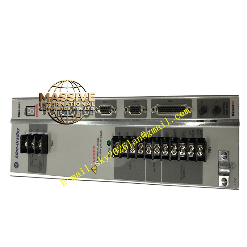
Description
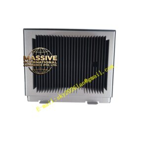
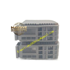
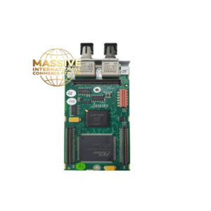
ABB PCD235A101
- Technical Specifications (typical PCD235A101 — verify against label):
- Power Supply: 24 V DC (18–30 V), typ. 8–12 W
- Onboard DI: 8/12/16 × 24 V DC (wet/dry selectable per group) — debounce 0–127 ms
- Onboard DO: 4/6/8 × Relay SPDT (2 A @ 250 V AC) or Transistor (0.5 A @ 24 V DC) — model dep.
- Onboard AI: 2/4 × 0–10 V / 4–20 mA (12-bit)
- Onboard AO: 2 × 4–20 mA (12-bit)
- Communication Ports:
- Eth: 10/100 Base-TX (RJ45) — Modbus TCP Server/Client, optionally IEC 61850 (firmware opt)
- RS-232: D-sub 9 (service / local HMI)
- RS-485: Screw terminals or D-sub — Modbus RTU Master/Slave
- Program Memory: ≥512 kB user logic; retain variables battery-backed
- Battery: CR2032 or Varta cell on CPU — retains retentive vars ≥5 yr
- LEDs: Run, Err, I/O Active, Com, Link (Eth)
- Mounting: DIN rail 35 mm (compact ~90×100×70 mm)
- Operating Temp.: 0 °C to +55 °C (–20 °C to +70 °C storage)
- Certifications: CE, UL, cUL, GL (marine some versions)
- Functional Features:
- Integrated I/O eliminates need for separate I/O rack for small skids
- Web server (some FW) — view process values via browser
- Time sync via NTP/SNTP (Ethernet) or IRIG-B (if ext. option)
- Expandable via Modbus RTU to remote small I/O drops (e.g., ABB S200 / S500 remote I/O)
- Password protection for upload/download & online change
- Application Scenarios:
- Boiler auxiliaries (fan start/stop sequencing, damper control, low‑level interlock)
- Water treatment (pump lead‑lag, chemical dosing pump control, tank level interlock)
- Package compressor / chiller skid control (communicates setpoints to onboard compressor controller via Modbus RTU)
- Retrofit of obsolete PLC5 / S5 with modern ABB Compact 800
- Material & Structure:
- Housing: Gray polyamide (PA66) UL 94 V-0 with label pocket
- Removable screw terminals (DI/DO/AI/AO/Power/RS-485)
- DIN clip (top & bottom — lock levers)
- Front: LEDs + RJ45 + D-sub 9 (RS-232)
- Working Principle:
Cyclic execution: Read onboard DI & AI → execute user logic (IEC 61131-3) → update DO & AO → exchange data via Ethernet/RS-485 (Modbus polls / IEC 61850 MMS) → repeat scan (typical 10–100 ms scan time settable). Retentive variables preserved across power cycles (battery-backed RAM + flash backup on download).
- Installation Requirements:
- Mount on 35 mm DIN rail in panel — leave top/bottom space for wiring & ventilation
- Connect 24 V DC plant PSU (+ / –) to Power terminals — fuse 2 A slow-blow typical
- Wire field DI (dry contact between Ix & C) — for N.C. E-Stop wire accordingly & invert in logic
- Wire DO to load (e.g., contactor coil via interposing relay if >2 A AC3) — note relay contact rating (2 A resistive)
- Wire AI (4–20 mA Tx loop-powered: PSU+ → Tx+ → Tx– → AI+ → AI– → PSU–; for V: signal +/– to AI+/AI–)
- Connect Ethernet to plant switch / HMI; RS-485 to drives/HMI as needed
- In Control Builder M: create “Compact 800” project → select PCD235A101 → define I/O mapping → write logic → download
- After download: verify Run LED solid green; force DI/DO to test; monitor AI values with simulator signal (mA calibrator / pot)
- Replace battery every 3–5 yr (or per PM schedule) — with power ON (hot-swap) to preserve retentive vars; after new battery verify no “Battery Low” LED
- Precautions:
- Battery: If battery dies with power off → retentive vars lost → controller may start with default / force init values per your program design — best practice: on first power-up after battery change force re-init or download known-good values
- Onboard DO Rating: Relay contacts 2 A — for contactor / solenoid >2 A AC3 use interposing relay (ABB K-series etc.) driven by PCD DO
- AI Shunt: For 4–20 mA — ensure internal shunt jumper selected (if present — some PCD have fixed 250 Ω; some have software selectable — check manual)
- Firmware Compatibility: Control Builder M version must support PCD235 FW — if mismatch prompt to update FW (requires online connection & may reset app — backup first)
- Keep project (.acp) & parameter printout on file server