Description
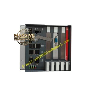
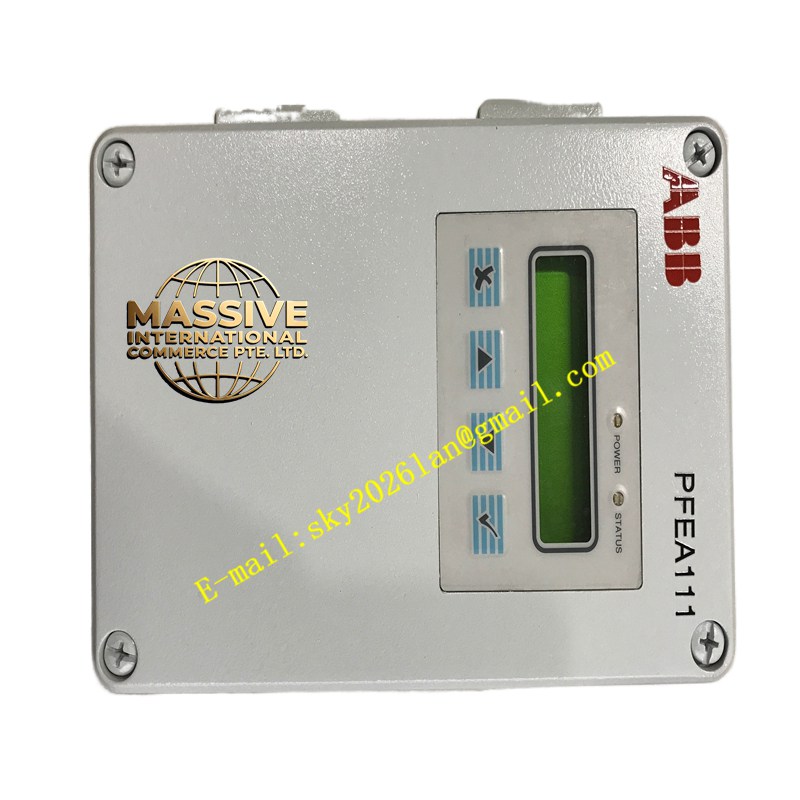
ABB PFEA111-65
- Technical Specifications (typical PFEA113 — PFEA111 subset of this):
- Input: From Pressductor PillowBlock — excitation output 5–10 V rms AC (2–5 kHz square); signal input ±50 mV to ±500 mV (auto-ranged)
- Output (Analog): 2 × (or 1 ×) 4–20 mA (active, isolated) & ±10 V (isolated) — scalable to F.S. force (e.g., 0–10 kN = 4–20 mA)
- Accuracy: ≤0.1 % of F.S. (typical) including linearity, hysteresis, repeatability
- Alarm Relays: 2–3 × SPDT (form C) — rated 5 A @ 250 V AC — typical uses: Web Break (Lo Lo), Overload (Hi Hi), Fault
- Tare / Preset: Pushbutton or external contact — stores current reading as zero (with max tare % limit to prevent gross error)
- Display: 5-digit LED or 20-segment bar graph (PFEA113); PFEA111 may have bar graph only
- Power Supply: 24 V DC (18–30 V) — typ. 5 W
- Operating Temp.: 0 °C to +50 °C (–20 °C to +70 °C storage)
- Mounting: DIN rail 35 mm or panel (with bezel — some versions NEMA 1 panel mt)
- Dimensions: ≈45 mm (W) × 110 mm (H) × 120 mm (D) (typical DIN version)
- Certifications: CE, some versions ATEX / IECEx for use with Ex-i barrier (Pressductor PillowBlock itself usually Ex-e / Ex-i compatible — check PFTL cert)
- Options (implied by -65 / -20 suffixes): -65 often = 4–20 mA + relays + no fieldbus; -20 often = dual-ch + relays + possibly Profibus/DevNet option fitted — verify by checking option sticker
- Functional Features:
- Web Break Detection: If measured force drops below Break % of FS for >Break Time (adjustable 0–5 s) → Web Break relay operates → can trip unwind/winder drives
- Tare with Limit: Prevent accidental tare at loaded roll — set max tare % (e.g., 10 % FS) — if tare attempted >limit → ignored / alarm
- Peak Hold: Capture max tension during transient (e.g., start-up snatch) — view on display or via analog output hold
- Diagnostic LEDs: Show signal level, excitation OK, sensor open/short, alarm active — speeds commissioning
- Fieldbus (if option fitted): Read tension value, alarm status, perform tare, change setpoints via Profibus DP / DeviceNet / Modbus RTU
- Application Scenarios:
- Web handling lines (paper, film, foil, steel strip): measure & control strip tension at bridle/nip/winder/unwinder
- Press force monitoring (metal forming press — PFEA113 peak hold captures max press force)
- Cable/polyester yarn tension in textile/rope mfg
- Paired with PFTL201C PillowBlock load cells (see next item)
- Material & Structure:
- Housing: Polyamide (PA66) DIN case — gray RAL 7035, transparent front cover
- Terminals: Screw (removable plug-in) — Excite+/-, Sig+/-, 4–20 mA Out+/-, Relay C/NO/NC, 24 V DC In, Shield Drain (to earth bus)
- Internal: Precision AC excitation source, instrumentation amp, 16-bit A/D, microprocessor (PFEA113), isolated DC/DC converter
- Working Principle:
Pressductor PillowBlock contains a ferromagnetic core & coil — when compressive force applied → permeability changes → induces voltage in secondary coil (proportional to force × excitation). PFEA supplies AC excitation → measures induced signal → demodulates → linearizes per stored calibration → outputs scaled 4–20 mA / ±10 V. Tare subtracts no-load offset. Alarm logic evaluated each scan → relay states updated.
- Installation Requirements:
- Mount on DIN rail in instrument panel near PillowBlock (keep cable ≤50–100 m; for longer use proper shielded twisted pair & check signal quality)
- Connect PillowBlock cables:
- Excite+ / Excite– → PFEA Excite terminals (check PillowBlock wiring diagram — some have 4-wire: 2 excite, 2 signal; some 6-wire incl shield)
- Sig+ / Sig– → PFEA Signal terminals
- Shield → PFEA Shield terminal → bond to panel PE bus (star ground)
- Connect 24 V DC PSU (fused)
- Connect 4–20 mA to DCS/controller AI (2-wire loop-powered typical — PSU+ → AI+ → PFEA Iout+ → PFEA Iout– → AI– → PSU–)
- Power up → perform auto-zero (tare) with web slack / roll removed (no tension) → set Full Scale Force in menu (e.g., 10 kN)
- Apply known calibration weight or known roll → verify mA output matches (e.g., 5 kN → 12 mA)
- Set Web Break % (e.g., 5 % FS for <0.5 s) & Overload % (e.g., 110 % FS) → verify relay operation
- For dual PFEA113: can sum two PillowBlocks (left+right of roll) → total tension = sum; differential = left–right → can detect off-center loading
- After commissioning: lock parameter access (password) — record tare value & FS setting
- Precautions:
- Shield Grounding: PillowBlock signal & excite cable shield drained to PFEA Shield terminal ONLY (one end) → panel PE — do NOT ground at PillowBlock end (may be already grounded via press frame — check; if frame grounded ok but typically shield drain at PFEA only to avoid ground loops)
- Tare with Web Present: Never tare with web under tension — gives false zero → all readings offset. Best practice: tare with rolls empty / web cut & slack (no wrap tension)
- Cable Length / Noise: Long cables pick up EMI — route separate from VFD output ≥300 mm; cross at 90°. If noisy signal — check shield continuity & consider signal filter time constant in PFEA menu (increase slightly — trade-off response time)
- PillowBlock Orientation: PFTL201C must be loaded purely in compression along axis — side loads / moments degrade accuracy & may damage — follow ABB mounting torque & load introduction instructions
- Replace PFEA: After swap → re-enter FS value & re-tare (tare stored in PFEA NVRAM — new unit needs re-entry); verify alarm setpoints copied from old unit label/photo