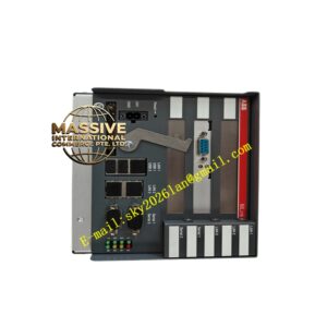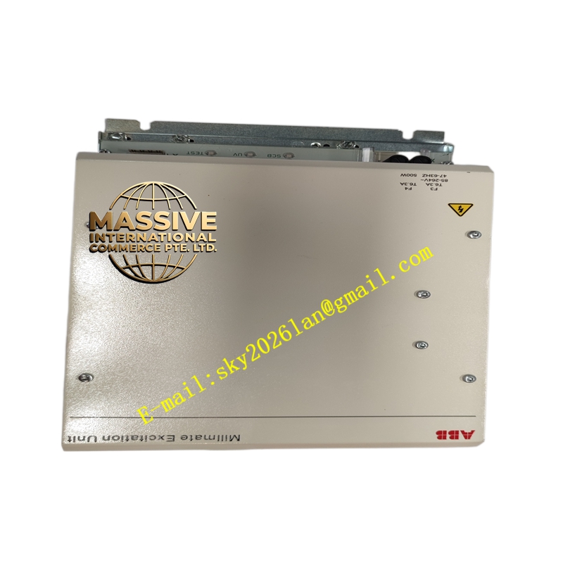
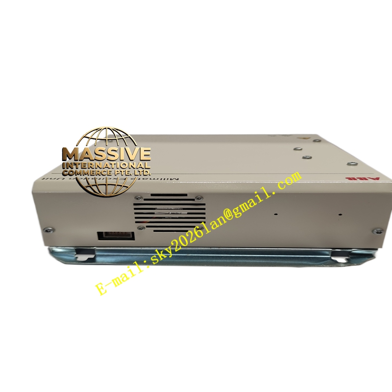
Description
ABB PFVI401
- Technical Specifications (typical):
- Input Signal: 0–10 V DC, 0/4–20 mA (selectable)
- Display: 4–5 digit 7-segment LED, ±19999 count; selectable decimal point
- Engineering Units: Programmable — N, kN, lbf, kgf (via DIP or menu)
- Setpoint Function: 1 or 2 setpoints (Hi / Lo) with relay outputs (SPDT 250 V AC 2 A typical)
- Power Supply: 100–240 V AC or 24 V DC (model dependent)
- Accuracy: ±0.2 % of FSD + input accuracy
- Mounting: Panel cutout (96 × 48 mm DIN 43700) or DIN rail with bezel
- Operating Temp.: –10 °C to +50 °C
- Dimensions (behind panel): ≈90 × 45 × 110 mm
- Functional Features:
- Large bright LED for operator visibility on line
- Alarm relays can trigger slack-web alarm (Lo) or web break / over-tension (Hi) → stop machine or reduce speed
- Trend indication via bar graph (on some versions)
- Can be daisy-chained — multiple PFVI units on same analog signal for distributed readouts
- Application Scenarios:
- Operator display at unwind / rewind stand showing current tension
- Tension deviation alarm — e.g., Lo alarm → “Web Slack” → initiate re-thread sequence
- Companion to PFSA140 in older tension cabinets where digital display not on amplifier
- Material & Structure / Working Principle / Installation / Precautions:
- Mount in operator panel cutout; wire analog input from PFSA140/PFTL301E output; wire relay contacts to machine PLC/alarm annunciator
- Set display range & units to match transducer rated load (e.g., 0–5000 N for 5 kN PFRL)
- Adjust Hi/Lo setpoint pots or via keypad if version allows
- Precaution: If used with alarm relays — test Hi/Lo function during commissioning; ensure alarm logic in PLC matches relay NO/NC wiring (typically NC for fault-safe — alarm contact closes on fault; verify per machine safety requirement)