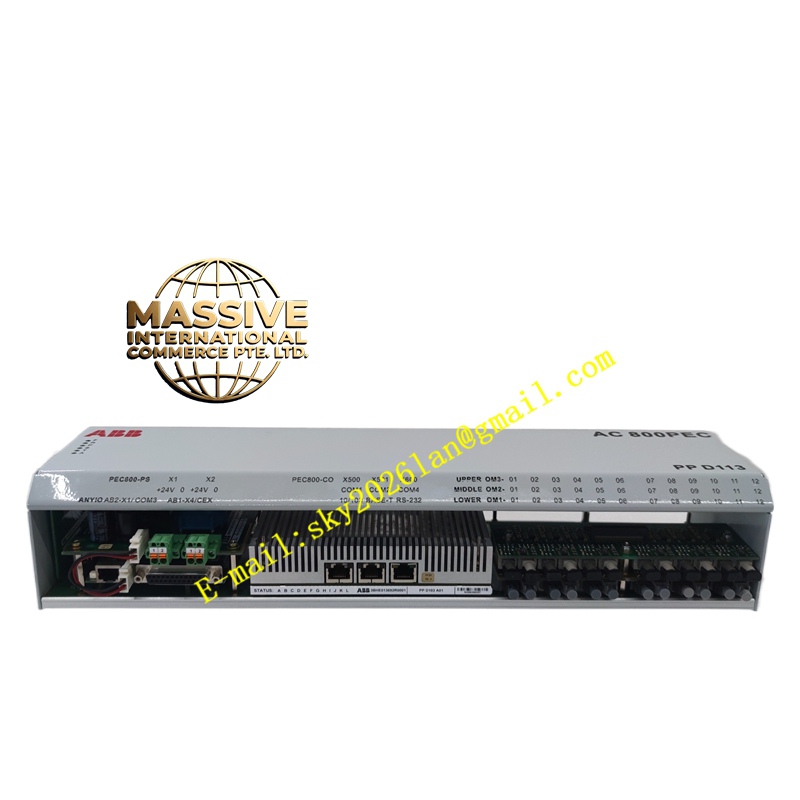
Description
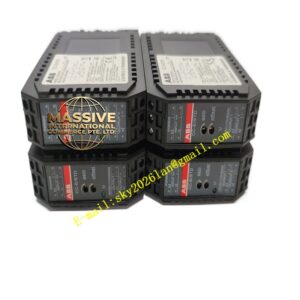
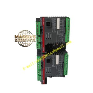
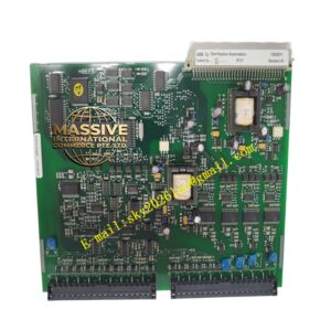
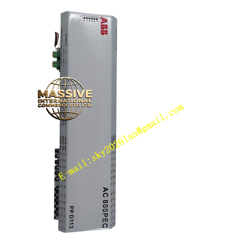
ABB PPD113A01-10-150000
- Technical Specifications (typical PPD113A01):
- Input Voltage: 24 V DC (18–30 V DC) — system / field supply from plant PSU (DSSR122 / third-party 24 V DC PSU)
- Output Logic (5 V DC): 5 V ±2 %, max 3 A (sufficient for typical S800 rack with 8–10 modules); short-circuit protected
- Output Process (24 V DC): Pass-through from input (fused or unfused depending on version) — feeds UP terminals on each TU in rack via bus bar or jumper
- Redundant Input: Dual 24 V DC inputs (A/B) with diode OR-ing — supports N+1 PSU redundancy
- Alarm Contact: 1 × SPDT relay (NO/NC) — closes on PSU healthy or opens on fail (configurable polarity)
- Power Dissipation: <10 W (quiescent + load dependent)
- Mounting: On S800 I/O rack — leftmost or designated power module position; DIN rail or direct bolt to TU end-plate
- Indicators: Input Power OK (green), 5 V OK (green), Fault (red)
- Operating Temp.: 0 °C to +55 °C
- Dimensions: ≈45 mm (W) × 119 mm (H) × 102 mm (D) — matches S800 TU width
- Certifications: CE, UL, cUL, ATEX Zone 2, marine
- Functional Features:
- Eliminates need for separate 5 V DC brick PSU — internal regulator derives 5 V from 24 V DC input
- Redundant 24 V DC input allows N+1 PSU configuration for high-availability I/O
- Alarm relay can be wired to DCS DI or annunciator for “I/O Rack Power Fail”
- Compatible with all S800 I/O modules(DI8xx/DO8xx/AI8xx/AO8xx)
- Application Scenarios:
- Every S800 I/O rack requires a PPD unit (or PS13-type power feed) — PPD113A01 is the standard for single/dual 24 V DC supply
- Redundant PSU feeding (two 24 V DC PSUs → PPD113A01 A/B inputs → I/O rack stays alive if one PSU fails)
- Retrofit of older S800 rack — replace failed PPD113 or upgrade from external 5 V PSU to integrated version
- Material & Structure / Working Principle / Installation / Precautions:
- Mount PPD113A01 on left end of I/O stack (engages with TU end-plate or DIN rail)
- Connect +24 V DC (A & B if redundant) to terminals observing polarity; connect PE to PE terminal
- Verify 5 V OK LED illuminates after power-on — if not, check input voltage & fuse
- Wire UP (process 24 V) from PPD to first TU’s UP terminal; subsequent TUs often link via bus bar
- Precautions:
- Total 5 V load = sum of all modules’ logic current (typ. 80–150 mA/module) — PPD113A01’s 5 V regulator rated for typical rack; for very large racks (>12 modules + high-density) verify 5 V current budget — may need PS14 (higher current)
- Do NOT apply >30 V DC to 5 V terminals — regulator damaged
- If using redundant PSUs: size each PSU for 100 % load + margin — diode OR means both share load; if one fails other must carry full load
- Alarm contact wiring: test during commissioning — PSU fail should generate visible alarm in DCS