Description
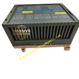
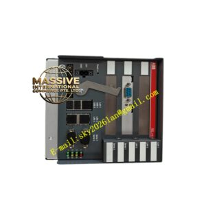
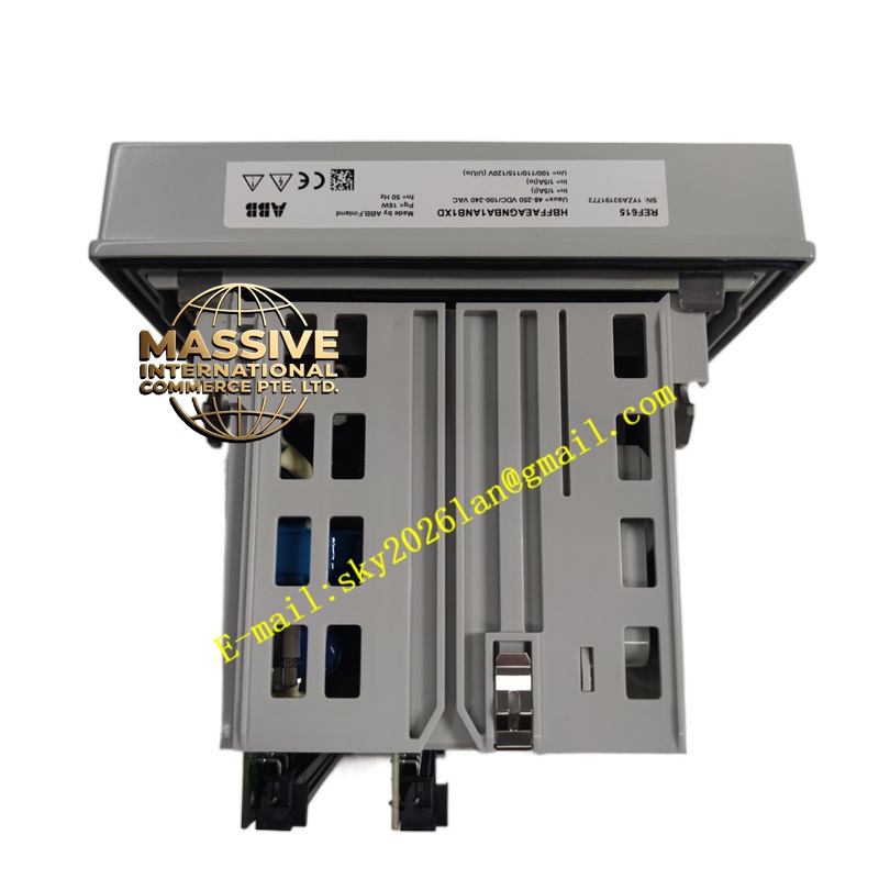
ABB REF615 HBFFAEAGNBA1ANB1XD
Technical Specifications:
- Protection Functions: Directional/non-directional overcurrent, sensitive ground fault, thermal overload, and breaker failure protection.
- Measurement Capabilities: True RMS measurement of all electrical parameters, including harmonic distortion up to the 63rd order.
- Communication Interfaces: Dual Ethernet ports supporting IEC 61850, Modbus TCP/RTU, and DNP3 over TCP/IP.
- Digital I/O: Extensive configurable binary inputs and outputs for custom control and signaling logic.
Functional Features:
- Customizable Logic: Utilize the PCM600 signal matrix and graphical logic editor to create complex, multi-layered protection and control schemes using timers, triggers, and boolean operators.
- Condition Monitoring: Built-in tools for continuous feeder health monitoring, including cable capacitance estimation and insulation degradation tracking.
- Fast Fault Location: Advanced algorithms calculate the distance to short-circuit and ground faults, guiding maintenance crews directly to the problem area.
- Redundant Power: Internal dual power supply inputs ensure uninterrupted operation during auxiliary power source failures.
Application Scenarios:
- Industrial manufacturing plants with complex motor and transformer loads.
- Utility substations requiring high-selectivity ground fault protection in compensated networks.
- Railway traction power supply systems.
- Commercial building power distribution and backup generation systems.
Performance Parameters:
- Adaptive Protection: Capable of dynamically adjusting protection settings based on real-time grid conditions or distributed generation status.
- Data Integrity: CRC checking and sequence numbering on all communication protocols to guarantee data integrity.
- Operating Temperature: Wide operating temperature range (-40°C to +70°C) suitable for extreme outdoor or unconditioned indoor environments.
- Electromagnetic Compatibility: Exceeds IEC 61000-4 Level 4 requirements, ensuring stable operation in harsh industrial environments with heavy switching transients.
Material Composition & Structural Characteristics:
- Front Panel: Intuitive membrane keypad with tactile feedback and a high-contrast LCD display for easy local operation.
- Backplane Connectors: Gold-plated edge connectors ensure reliable, low-resistance connections to the switchgear wiring harness.
- Internal Architecture: Modular hardware design separating power, analog input, processing, and output stages to minimize cross-interference.
- Labeling: Clear, permanent silk-screened labeling on the front panel and terminal blocks for quick identification during maintenance.
Working Principle:
The relay acts as the central intelligence for the feeder bay. It continuously acquires electrical data and evaluates it against multiple, overlapping protection zones. When a disturbance occurs, the relay determines the fault type, direction, and location. It then executes the appropriate control action, such as tripping a breaker, sending a GOOSE message to adjacent relays, or logging an event. The customizable logic engine allows users to interlock these actions with external binary inputs, creating a highly tailored protection strategy.
Installation Requirements:
- Clearance: Maintain adequate clearance around the relay for proper airflow and safe access to terminal blocks.
- Cable Routing: Separate high-voltage primary cables from low-voltage secondary control and communication cables to prevent inductive coupling.
- Grounding: Connect the relay ground terminal to the substation ground grid using a short, heavy-gauge copper conductor.
- Software Tools: Ensure the engineering workstation has the latest version of PCM600 installed for configuration and offline simulation.
Usage Precautions:
- Logic Verification: Thoroughly test any custom logic created in the signal matrix using offline simulation before deploying to the live relay.
- Firmware Compatibility: Verify that the relay firmware version is compatible with the PCM600 software version to prevent communication or configuration errors.
- Routine Maintenance: Perform annual visual inspections of terminal connections and verify the functionality of the self-monitoring alarms.
- Authorized Personnel: Only trained and authorized personnel should perform configuration changes, testing, or maintenance on the relay.