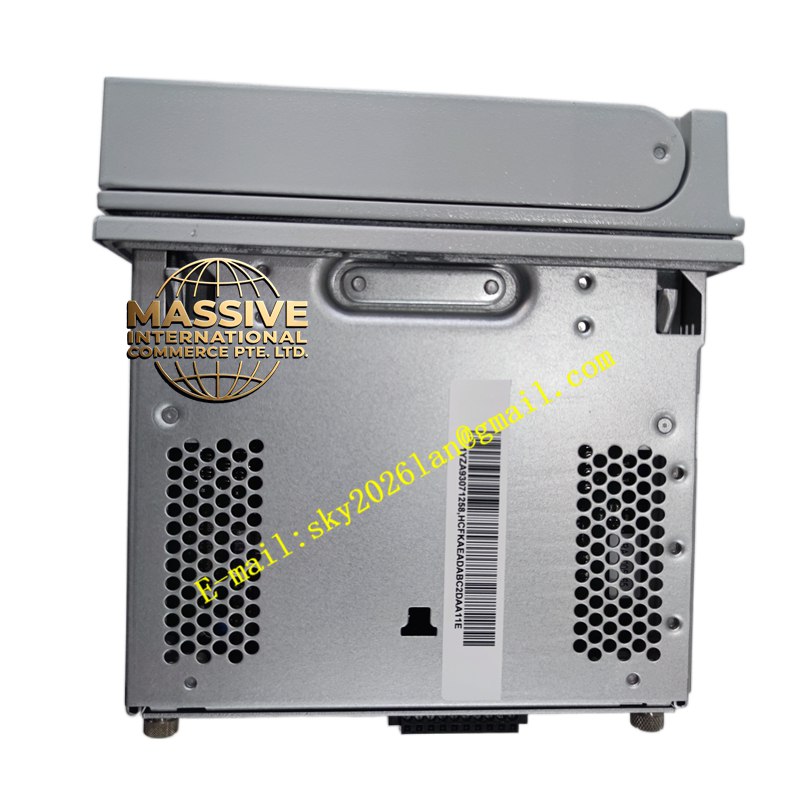
Description
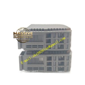
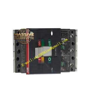
ABB REF615
- Technical Specifications (typical REF615 panel version — compact version similar electrically):
- Current Inputs: 3 × phase CT (1 A / 5 A selectable, burden ≤0.1 VA @1A / ≤0.2 VA @5A), 1 × residual CT / core-balance CT (I0)
- Voltage Inputs: 3 × phase VT (100 / 110 / 120 V L-L), 1 × Vn (4-wire optional); burden ≤0.2 VA
- Protection Elements: 51/67, 51N/67N, 46, 49, 27/59, 81O/U, 79, 50BF, 25 (opt), VTFF
- Binary Inputs: 8 / 12 / 16 (model dep.) — wet (110/220 V DC) or dry (24 V DC) — programmable function
- Binary Outputs: 8 / 12 / 16 — SPDT/SPST; Trip ×2 (redundant), Close, Alarm, Healthy, Test
- Trip Contact Rating: 5 A @ 250 V AC / 30 V DC (make & break — verify per label)
- Display: Graphical LCD (320×240 monochrome or 640×480 color — model dep.) + keypad
- Power Supply: 110/220 V DC ±20 % or 230 V AC ±15 % (dual redundant option)
- Time Sync: IRIG-B, SNTP, PTP (IEEE 1588 v2 — option)
- Disturbance Recorder: ≥50 records; pre-fault ½ cycle + post-fault; 4 kHz sampling
- Case: 4U half-rack 19″ panel-mount (REF615 panel) OR DIN-rail compact (REF615 Compact — approx 105 × 175 × 145 mm)
- Operating Temp.: –20 °C to +55 °C
- Certifications: IEC 60255, IEC 61850-3/5-7, IEEE C37.90, KEMA type-tested, CE, UL, cUL
- Engineering Tool: ABB PCM600 (Protection & Control Configuration Tool) — SCL import/export
- Functional Features:
- Dual setting groups (easy switch for radial ↔ looped or summer/winter CT ratio)
- Local/Remote control with key-switch input
- IEC 61850 GOOSE publish/subscribe — e.g., receive bus differential block signal, send breaker failure status
- Thermal image with cold-load pick-up & reset
- Password-protected multi-level access (Operator / Engineer / Service)
- Integrated self-test & watchdog; PSU fail contact
- Application Scenarios:
- 11–33–66–132 kV radial or ring-main feeder OC & EF protection
- Transformer LV side protection (OC + EF + thermal + inrush blocking from HV side differential)
- Industrial substation outgoing feeder with integrated control & SCADA reporting
- Retrofit of electromechanical OC-G / EF relays + separate ammeter/voltmeter + control switches — single device replacement
- Material & Structure:
- Panel version: Sheet steel / aluminum 4U case, gray (RAL 7035), transparent Lexan front window, plug-in rear terminal blocks (keyed)
- Compact (DIN): Flame-retardant polycarbonate/ABS housing, DIN-rail clip (35 mm), front LEDs + mini-LCD (some versions text-only; full graphics via PCM600 or web interface)
- Internal: 32-bit processor, 24-bit A/D front-end, RTC with supercap backup (≥10 yr), galvanic isolation CT/VT ≥2 kV
- Working Principle (Protection Core):
- Sampling: CT/VT analog inputs sampled @ ≥24 samples/cycle → DFT extracts fundamental RMS & phase angle.
- Overcurrent (51/67): Compare RMS phase I to pick-up × time-dial curve (Std Inverse / Very Inv / Extremely Inv / Definite Time). If directional enabled → check angle between I & polarized V (or I0/E0 for EF) → only trip if inside characteristic sector.
- Earth Fault (51N/67N): Residual I0 = Ia+Ib+Ic (or core-balance CT) → RMS compared to pick-up (can be 10–200 %In — sensitive for compensated networks). Directional EF uses V0 polarization.
- Thermal (49): I²R heating integrated; cooling per exponential (τ = thermal time const); alarm @ e.g. 90 %, trip @ 100 % of thermal limit.
- Auto-Reclose (79): On trip → dead-time timer → close cmd → if fault persists → lockout after N attempts; if successful → reset.
- Trip decision → close Trip relay contact → breaker trips.
- Installation Requirements:
- Mount panel version in 19″ cubicle (leave rear clearance); compact version on DIN rail in LV panel.
- Wire CT secondaries (polarity! S1→Ia+, S2→In/com) — short CTs before disconnecting relay.
- Wire VT secondaries (fused 0.5 A HRC) — verify polarity.
- Connect DC supply (+ / –) & PE.
- Wire BI (52a/b, ext trip/block, local/remote sel) & BO (Trip in series with breaker coil + sealing relay / anti-pump, Close, Alarm).
- Connect Ethernet (IEC 61850) or serial (103/104) to station bus.
- In PCM600: create REF615 project → enter CT/VT ratios, pick-up / TMS / direction / reclose params → download → perform secondary injection test (OC pick-up, EF pick-up, directional polar plot, reclose sequence) → verify.
- After test → authorize for service.
- Precautions:
- CT Secondaries: NEVER open energized CT — lethal HV & CT damage. Short CT secondaries with test link until relay connected & verified.
- VT Polarity: Reversed VT → directional/voltage elements mis-operate — verify during secondary injection.
- Settings: Must be reviewed by protection engineer; retain signed copy with relay serial # & FW version.
- Test Before Live: After any setting change or replacement → secondary injection test BEFORE closing breaker onto live line.
- Cyber (if Ethernet): Change default passwords; disable unused protocols; enable audit log per site policy.