Description
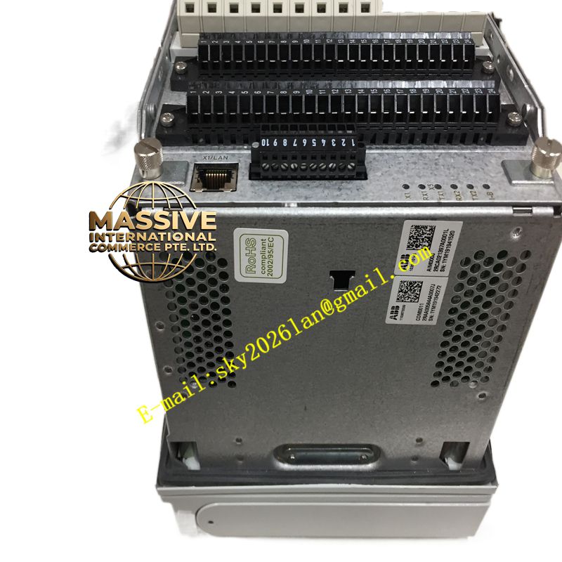
ABB REF615E-G HBFEAEAGNDA1ABA1XG
Technical Specifications:
- Input Voltage: 100, 110, 120, 220, 240 V AC (50/60 Hz); 48, 60, 110, 125, 220, 250 V DC.
- Maximum Permissible Interruption Time: 50 ms at rated auxiliary voltage.
- Auxiliary Voltage Fluctuation Range: 38-110% Un (38-264 V AC); 80-120% Un (38.4-300 V DC).
- Startup Threshold: DC < 13.0 W (rated) / < 18.0 W (max); AC < 16.0 W (rated) / < 21.0 W (max).
- Fuse Type: Type 1.
Functional Features:
- Comprehensive Protection: Provides directional and non-directional overcurrent and earth-fault protection, alongside voltage, frequency, and power-based protection.
- Advanced Earth-Fault Protection: Features a unique multi-frequency admittance-based protection portfolio for enhanced sensitivity and selectivity.
- Communication Protocols: Supports IEC 61850 Editions 1 and 2, IEC 60870-5-103, Modbus, and DNP3. Includes GOOSE messaging and IEC 61850-9-2 LE.
- User Interface: Equipped with a large graphical display for customizable Single-Line Diagrams (SLDs) and a web-browser-based HMI.
Application Scenarios:
Widely deployed in utility substations, power plants, oil and gas facilities, chemical plants, metallurgy, and water treatment plants for distribution system protection and control.
Performance Parameters:
- Dimensional Specifications: Rack 177 mm x Case 164 mm x Rack 177 mm x Case 160 mm x 201 mm.
- Weight: Total unit 4.1 kg; Plug-in unit 2.1 kg.
- Optional Features: Advanced and fast fault location for short circuits and earth faults, arc protection, and high-speed outputs.
Material Composition:
Encased in a ruggedized, industrial-grade metal enclosure designed to withstand harsh substation environments, featuring high-quality internal solid-state components and precision measurement transformers.
Structural Features:
Features a highly compact and versatile withdrawable plug-in unit design, allowing for swift installation, testing, and replacement procedures without extensive rewiring.
Working Principle:
Continuously samples three-phase currents and voltages via integrated sensors or conventional instrument transformers. An internal digital signal processor analyzes these waveforms against configured protection curves and logic, executing trip commands to circuit breakers upon detecting faults while simultaneously logging data for remote monitoring.
Installation Requirements:
Designed for standard rack or panel mounting. Requires secure backplane connection and proper termination of current and voltage circuits. Adequate ventilation must be maintained around the device.
Usage Precautions:
Always verify the specific order code to ensure the hardware matches the required protection functions. Never open the CT secondary circuit while the device is energized. Perform secondary injection testing to verify protection settings before primary energization.