Description
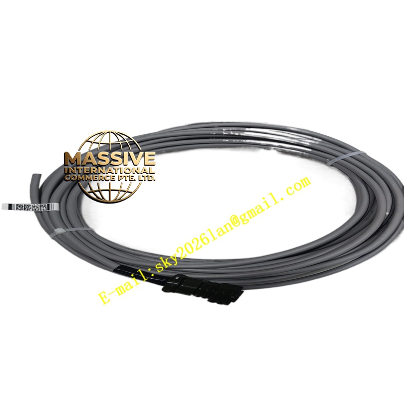
ABB RVVP-TPE
- Technical Specifications (typical ABB-recommended instrument cable for S800 I/O / HART):
- Conductors: Annealed copper, Class 5 flexible (stranded)
- Conductor Size: 0.5 mm² / 0.75 mm² / 1.0 mm² / 1.5 mm² (1.5 mm² typical for 4–20 mA with long runs; 0.75–1.0 mm² for TC/RTD)
- Insulation: PVC or PE (color-coded per pair: white/black, white/red…)
- Pair Shielding: Aluminum-polyester foil + tinned copper drain wire (0.5 mm²) + optional tinned copper braid (≥65 % coverage for high EMI areas)
- Overall Screen: Copper braid or foil (or both) — drain wire to cabinet earth
- Outer Sheath: TPE (Thermoplastic Elastomer) — oil/fat resistant, flame-retardant (IEC 60332-1), often LSZH (Low Smoke Zero Halogen) if specified for public buildings / tunnels
- Voltage Rating: 300 V / 500 V (inst conductor — NOT for power wiring)
- Operating Temp.: –30 °C to +80 °C (TPE); –20 °C to +70 °C (PVC)
- Characteristic Impedance (for Fieldbus H1): ≈100 Ω ±15 Ω (if specified as FF/PA cable — must meet IEC 61158-2Type A: 31.25 kbps, 100 Ω ±20 Ω, C ≤60 nF/km, L ≤0.65 mH/km)
- Functional Features:
- Low capacitance / low attenuation — suitable for HART (superimposed 1200 Hz FSK) & FF H1 (31.25 kbps)
- Braid + foil shield gives >60 dB immunity to VFD / switchyard EMI when properly grounded
- TPE sheath resists cutting oils, coolants, UV (some grades) — better than plain PVC in harsh plant areas
- Color-coded pairs simplify termination & loop tracing
- Application Scenarios:
- 4–20 mA analog signal wiring (S800 AI835 / HAI805 ← field transmitter) — 1 pair + shield per channel (or shared common in multi-pair)
- TC/RTD wiring — individual pair (or 3-wire RTD = 2 signal pairs + common) — use extension/compensating wire type if TC (Cu-Cn for Type T, Ni-Cr/Ni-Al for K etc.) — for long runs consider Cu extension wire in same shield type
- FOUNDATION Fieldbus H1 / Profibus PA — Type A cable per IEC 61158-2(100 Ω, low cap) — must be certified FF cable if used for H1 segment
- Discrete 24 V DC DI/DO wiring in noisy environments (shielded pair even for DI — reduces induced noise on long runs)
- Material & Structure:
- Conductor: Bunch-stranded annealed Cu
- Insulation: PVC (gray/colored) or PE (white/colored per pair)
- Pair: Twisted (≥25 twists/m for AI/TC; ≥40 twists/m for FF H1) — twisting reduces common-mode pickup
- Shield: Aluminum-polyester foil + tinned Cu drain wire (connected to earth at one end only — typically cabinet end); optional outer braid (tinned Cu)
- Outer Jacket: TPE (black or orange), embossed with cable spec & meter marks
- Working Principle (Shield Grounding):
Shield intercepts EMI (capacitively/inductively coupled from VFD output, switchyard, radio). The shield is connected to cabinet earth (PE busbar) at the DCS / I/O termination end ONLY (one-point ground) — drain wire stripped, crimped to fork lug, bolted to PE bar. At field instrument end, shield is insulated (drain wire NOT connected) to avoid ground loops. For FF H1 / PA segments: shield grounded at host end (linking device / power conditioner); field device end floating (unless IS barrier requires otherwise — follow barrier vendor instruction).
- Installation Requirements:
- Lay separate from VFD output / AC power cables — minimum separation 300 mm (cross at 90° if must cross)
- Use proper cable gland / PG-nipple with shield clamp (EMC gland that contacts braid) at cabinet entry — ensures 360° shield bonding to PE
- For multi-pair: use individual pair shields (drain to PE) + overall shield (also to PE) — both drain wires landed on same PE bar (star grounding)
- Verify continuity of shield/drain wire before termination — megger not needed; visual + ohmmeter OK
- For TC: if using Cu extension wire — keep type matching TC (J→J, K→K, T→T); if using thermocouple extension cable in same RVVP-TPEstyle — it is Cu alloy, NOT Cu — label clearly
- Precautions:
- One-Point Ground ONLY — grounding both ends creates ground loop → DC offset / noise on analog signals → erroneous readings
- Do NOT use for AC power, motor leads, or DC >60 V (except special ratings) — insulation not rated for mains
- For FF H1 / PA: must use certified Type A Fieldbus cable(100 Ω characteristic impedance, C ≤60 nF/km, L ≤0.65 mH/km, attenuation ≤3 dB @ 39 kHz) — not all RVVP-TPE qualifies; check spec / request FF-certified cable from vendor
- Avoid sharp bends (<4× cable Ø) — kinking breaks foil/shield & strains conductors
- In hazardous area (Zone 1/2): use cable with appropriate flame & gas-propagation rating (IEC 60332-3Cat C/D); for IS circuits ensure cable parameters compatible with barrier calculations