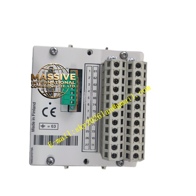
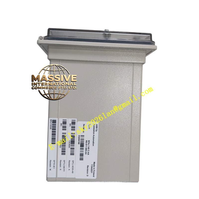
Description
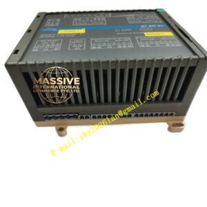
ABB SPAJ140C
- Technical Specifications (typical SPAJ140 / 140C):
- Current Inputs: 3 × phase CT (1 A / 5 A), 1 × residual / core-balance CT (I0); burden ≤0.1 VA @1A
- Voltage Inputs: None (SPAJ140) / 3 × phase VT 100 V + Vn (SPAJ140C with voltage option)
- Protection Functions: 51, 51N (67N on -C), 27 (opt), 50BF (basic), VTFF (opt)
- Binary Inputs: 4–6 (Ext Trip Block, Test, Local/Remote — wet 110/220 V DC or dry 24 V DC)
- Binary Outputs: 4–6 — Trip ×2 (redundant), Alarm, Healthy / Operate
- Trip Contact Rating: 5 A @ 250 V AC / 30 V DC
- Display: 2×16 alphanumeric LCD + LEDs + keypad
- Power Supply: 24/48/110/220 V DC or 230 V AC (model dependent)
- Operating Temp.: –20 °C to +55 °C
- Case: DIN-rail compact (≈105×90×75 mm) or panel ½-19″ (≈220×132×180 mm)
- Engineering: SPAsoft(DOS/Windows early tool) via front port or RS-485
- Certifications: IEC 60255, KEMA type-tested
- Functional Features:
- Dual setting groups (via DI or comms)
- Cold-load pick-up for thermal imitation (simplified vs. true 49)
- Local fault recall — shows pick-up current, operate time, fault type on LCD
- Password protection for setting changes
- Self-supervision & watchdog
- Application Scenarios:
- 3–33 kV MV feeder OC & EF protection (radial / loop)
- Transformer LV side OC+EF (no diff — that’s RET540/RET620)
- Industrial plant outgoing feeder where IEC 61850 not yet required (legacy plant)
- Retrofit / spare-for-existing SPA-installations (new projects → REF615)
- Material & Structure:
- Housing: Flame-retardant ABS/PC (DIN version) or sheet steel (panel); front Lexan window
- Terminals: Plug-in screw / spring-cage CT/VT/BI/BO — keyed (some versions)
- Internal: 16-bit A/D, 8-bit MCU (early gen), RTC backed by supercap
- Working Principle (same OC/EF as REF615 but less features):
- CT sampled → RMS computed → compared to pick-up × Time Dial curve → trip if persist beyond time
- Residual I0 = ΣIa+Ib+Ic (or core-balance CT) → EF pick-up; if directional EF enabled → check ∠(I0,V0) inside sector
- On trip → close Trip relay contact → breaker trips
- Event log stores last N trips (current, time, type)
- Installation Requirements:
- Mount DIN-rail or panel — leave rear access for CT/VT wiring
- Wire CT secondaries with correct polarity — short CTs before disconnecting relay
- If VT version (-C): wire VT fused (0.5 A HRC)
- Connect DC supply & PE
- Wire BI (52a/b, Ext Block) & BO (Trip in series with breaker coil + anti-pump; Alarm/Healthy to SCADA)
- Connect PC via front RS-232 → SPAsoft → enter CT/VT ratios, pick-up, TMS, EF sensitivity, DI/BO assignment
- Perform secondary injection test (OC pick-up & timing, EF pick-up, directional polar plot if -C) → verify before live close
- After test → authorize service
- Precautions:
- CT Safety: NEVER open energized CT — lethal HV & CT damage. Short CT secondaries with test link until relay connected & verified.
- VT Polarity (SPAJ140C): Reversed VT → directional EF mis-operates — verify during secondary injection.
- Settings: Must be reviewed by protection engineer; retain printed settings with relay serial # & FW ver.
- Legacy Product: SPA series is in limited / lifecycle / obsolete status in many regions — spares kept for existing plants; new designs should use REF615 (IEC 61850, better disturbance recording, GOOSE).
- No IEC 61850: If plant requires IEC 61850 — this relay cannot provide it — use REF615 or RET615.