Description
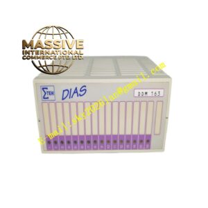
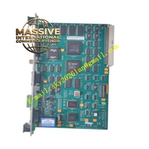
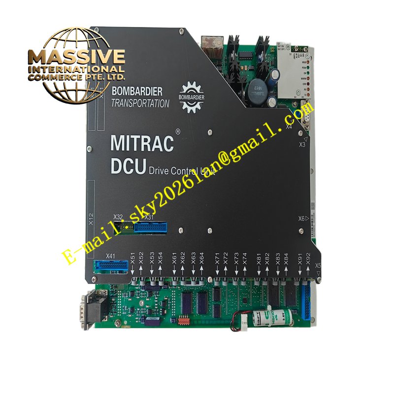
ALSTOM DCC2382A 3EST125-975
Technical Specifications On-board 24 V auxiliary power supply input from vehicle battery; galvanically isolated analogue measurement channels for motor current and DC link voltage; optical fibre output channels for IGBT gate drive; encoder signal interfaces for motor rotor position; hardware fault shutdown circuit; operating temperature -40 °C to +85 °C; conformal coated PCB; compliant with railway vibration and shock standards.
Functional Features High-speed closed-loop torque and speed regulation for traction motors; dynamic transition between traction, coasting and regenerative braking modes; DC link overvoltage suppression control; channelised fault diagnosis with non-volatile event logging; real-time data transmission to vehicle central control system; safe state implementation for emergency braking.
Application Scenarios Subway traction converter control cabinets, regional light rail propulsion systems, Alstom Mitrac platform rolling stock maintenance spare parts.
Material Composition Aluminium reinforced module frame; FR4 high-density multilayer PCB with moisture-proof conformal coating; wide-temperature industrial semiconductors; optical transceivers; vibration-proof multi-pin connectors; metal shielding components for electromagnetic interference suppression.
Structural Characteristics Horizontal chassis plug-in form for converter cabinet installation; front panel LED array for power, run and fault indication; rear heavy-duty connector assembly for vehicle wiring; internal physical separation of analogue measurement circuits, digital processing circuits and optical drive channels.
Working Principle The board receives traction or braking setpoints from the vehicle control unit and samples DC bus voltage, motor phase currents and rotor position signals. The control algorithm calculates pulse-width modulation patterns and transmits optical trigger signals to the power IGBT modules. Fault monitoring circuits continuously monitor critical variables and inhibit drive pulses once limits are exceeded.
Installation Requirements Install the board only after converter cabinet auxiliary power is isolated; tighten mounting fasteners to railway specified torque; check optical fibre end faces for contamination; route encoder cables in shielded twisted pair and separate from high-voltage traction cables.
Operation Notes Do not operate the board outside the defined vehicle auxiliary voltage range; store spare modules in temperature-controlled anti-static packaging; download fault history records before replacement; confirm vehicle safety interlock status before converter energisation.