Description
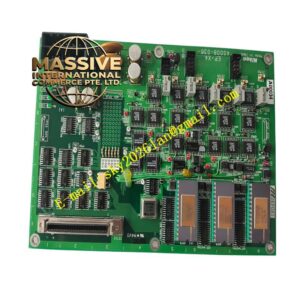
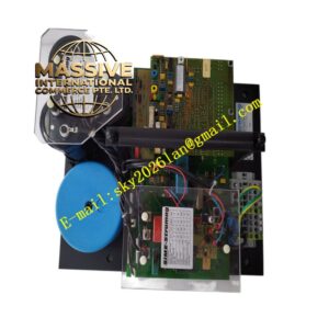
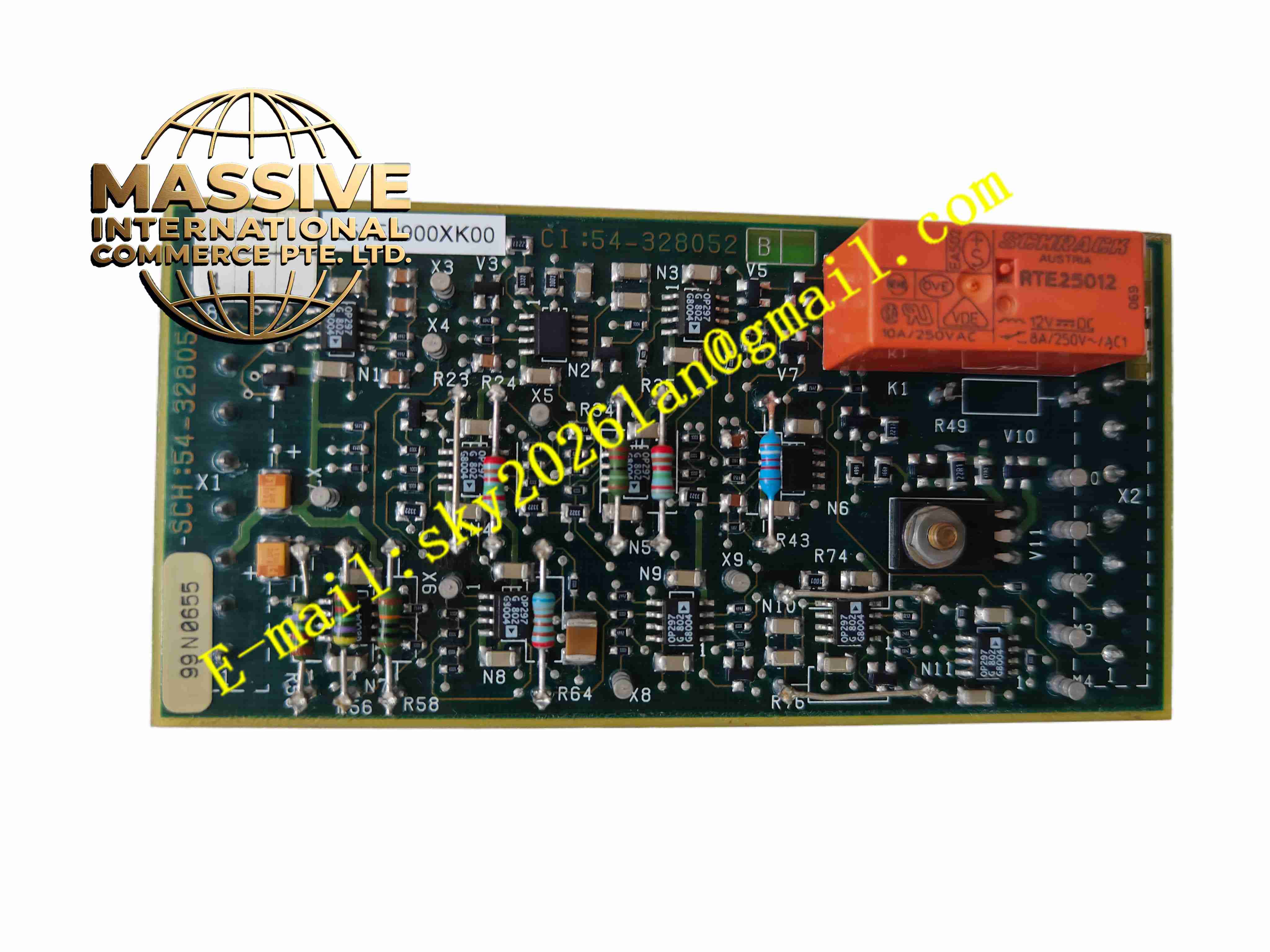
Alstom L54E2900XK00
Technical Specifications Multi-slot bus layout; integrated power distribution circuit and signal trace; rated working voltage 24V DC; signal bus differential transmission design; operating temperature -20°C to +70°C; insulation protection for power and signal traces; matched with Alstom standard rack mechanical size.
Functional Features Distribute 24V DC working power to each module slot in the rack. Establish high-speed parallel bus communication channels between different plug-in modules. Transmit address selection signals and diagnostic signals of each slot. Provide mechanical positioning reference for each module plugging position. Suppress partial conducted interference between power circuit and signal circuit. Support hot-slot diagnosis of module presence status.
Application Scenarios All types of Alstom control racks for thermal power, hydropower and substation automation cabinets.
Performance Parameters Stable power output for multi-module load; low signal attenuation on bus traces; consistent impedance matching for differential bus signals; long service life under continuous vibration and temperature cycling.
Material Composition Backplane PCB uses thickened FR-4 flame-retardant multilayer board; power traces adopt thick copper foil; connector sockets are nickel-plated copper alloy with gold-plated contact surfaces; board surface uses high-temperature resistant solder mask ink; fixing hardware adopts anti-corrosion alloy.
Structural Characteristics Horizontal fixed board installed at the rear of the control rack. Multiple module sockets are arranged in sequence corresponding to each rack slot. Edge fixing holes are used to fasten the board on the rack frame. External power terminals are reserved for rack power access. Bus traces are distributed inside the board to realize interconnection of each socket.
Working Principle External 24V DC power enters the power distribution circuit of the backplane and is distributed to each slot contact. The bus signal traces connect the gold finger sockets of all slots. When each module is inserted in place, the module communicates with other modules through the differential bus on the backplane, and obtains working power from the power contacts of the socket.
Installation Requirements Disconnect all rack power supplies before backplane disassembly and assembly. Fix the backplane board to the rack frame with specified torque of fixing screws. Check the contact condition of each socket after installation. Wire the rack main power supply to the reserved power terminals. Insert modules one by one and verify power supply and bus communication function.
Precautions for Use Do not scratch the gold-plated contacts of sockets during maintenance. Prevent conductive dust and metal debris from falling into socket gaps. Do not modify the wiring and traces of the backplane arbitrarily. Replace the whole backplane once socket pins are bent or burned.