Description
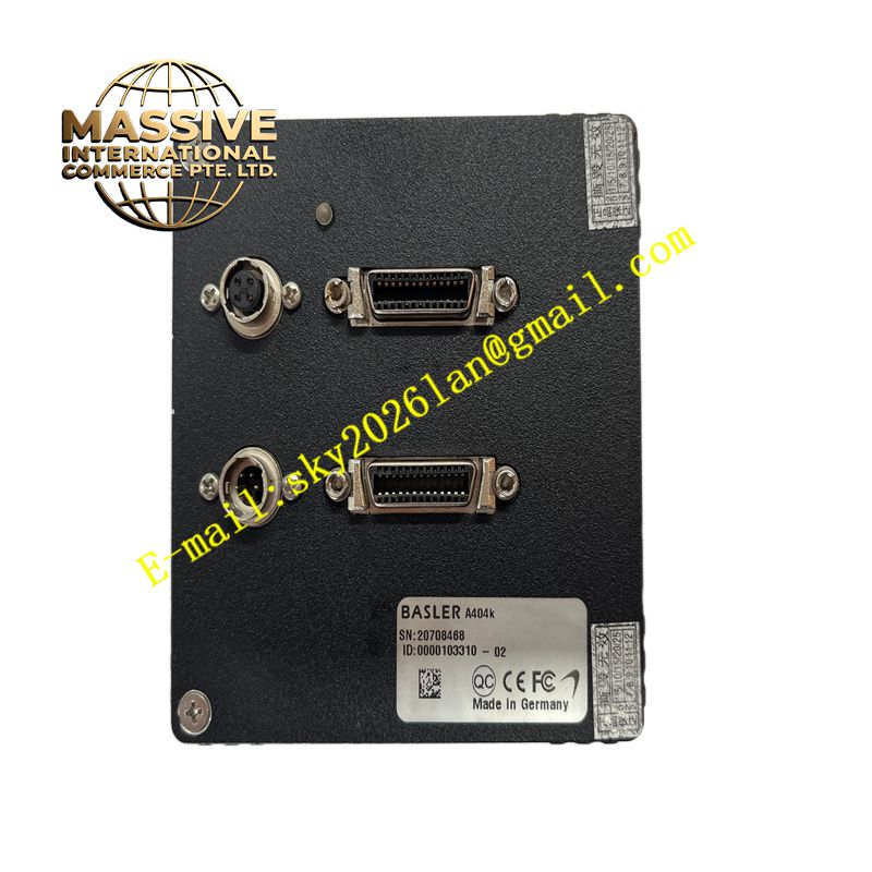
BASLER A404K
Technical Specifications Monochrome CCD image sensor; Camera Link LVDS data interface; adjustable gain and pixel offset; programmable exposure time; hardware trigger input and strobe output; C-mount lens interface; 12-bit digital pixel output; wide operating temperature range.
Functional Features Captures high-resolution grayscale images of workpieces under controlled lighting. Supports external hardware trigger to synchronize image capture with conveyor encoder or sensor signals. Provides adjustable analog gain and digital offset to optimize image brightness. Outputs pixel data in 8-bit or 10-bit or 12-bit selectable depth. Generates strobe signal to trigger light source synchronously with exposure window. Transmits image data to frame grabber over Camera Link bus.
Application Scenarios Electronic component defect inspection, dimensional metrology of machined parts, printed code reading, surface flaw detection, semiconductor wafer inspection, automated optical sorting stations.
Performance Parameters Low readout noise; high linearity of pixel response to light intensity; precise exposure timing control; stable image output under continuous cyclic triggering.
Material Composition Camera housing is machined aluminum alloy; image sensor is CCD silicon chip; lens mount is nickel-plated metal; internal circuit board is FR-4 multilayer PCB; connector shell is metal shielding housing.
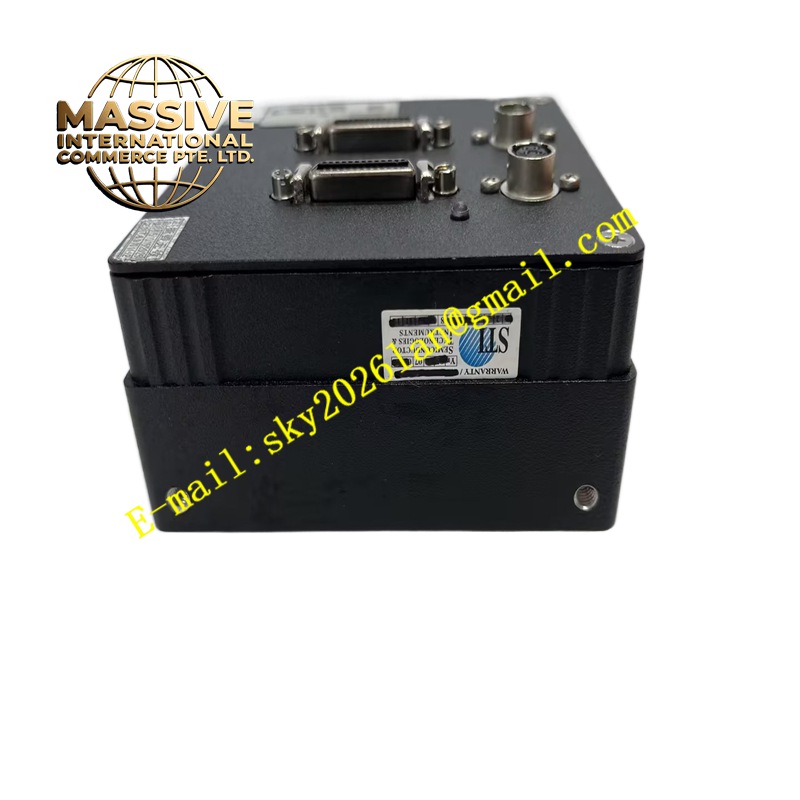
Structural Characteristics Compact box-style camera body; front C-mount lens thread; rear Camera Link data connector and power I/O connector; internal sensor assembly sealed against minor dust ingress; mounting threaded holes on camera housing for fixture installation.
Working Principle When receiving a trigger signal, the camera opens the electronic shutter for the programmed exposure duration. Light passes through the lens and projects onto the CCD sensor array. Photodiodes convert photon energy into proportional charge. After exposure completes, the sensor reads out charge row by row, converts charge values into digital pixel data and sends the full image frame over Camera Link LVDS differential lines to the frame grabber card in the host vision computer.
Installation Requirements Mount the camera on rigid vision fixture with vibration isolation if installed near cutting machinery. Select compatible C-mount lens and adjust focus and aperture for target working distance. Use shielded Camera Link cable with specified maximum length and match frame grabber configuration. Wire trigger sensor and light strobe signal to the camera I/O connector and set trigger mode in vision software.
Precautions for Use Do not touch the CCD sensor window with fingers or hard objects. Avoid direct strong laser illumination onto the sensor surface which causes permanent damage. Maintain clean lens and sensor window to prevent dust spots in captured images. Verify power supply voltage stays within camera specification range.