Description
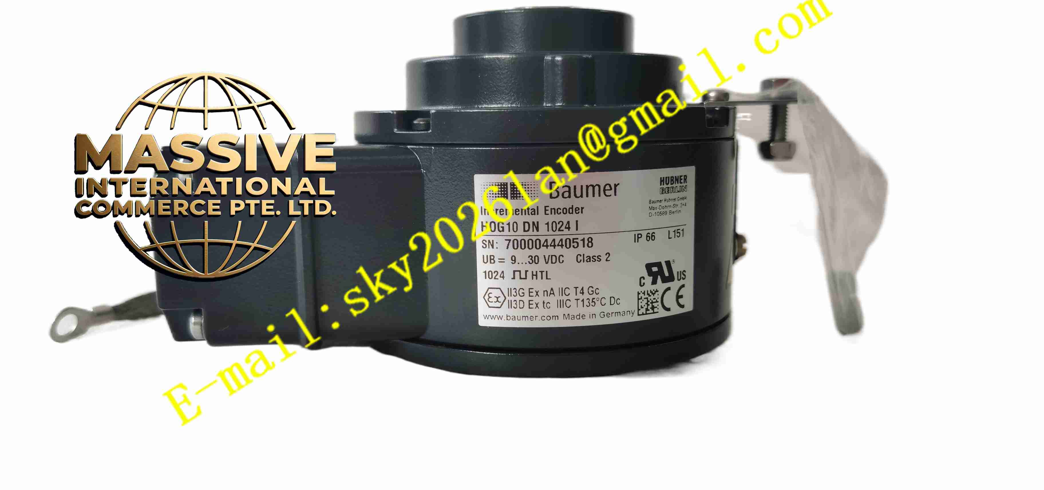
Baumer HOG10DN1024I
Technical Specifications
- Product Type: Heavy duty incremental optical encoder
- Pulses per Revolution: 1024
- Power Supply: 9 V DC to 30 V DC
- Current Consumption: ≤100 mA without load at 24 V DC
- Output Signal: HTL, A, B, Z and inverted complementary signals
- Phase Relationship: A and B channel phase shift 90° ±20°, zero pulse width 90°
- Maximum Output Frequency: 120 kHz
- Mechanical Max Speed: 6000 rpm
- Shaft Type: Blind hollow shaft, 16 mm bore diameter
- Permitted Axial Shaft Load: ≤450 N
- Permitted Radial Shaft Load: ≤600 N
- Protection Rating: IP66
- Operating Temperature: -40 °C to +100 °C
- Vibration Resistance: 5 g, 10 Hz to 2000 Hz
- Shock Resistance: 300 g, 6 ms
- Housing Material: Aluminium die-cast, shaft stainless steel
- Weight: Approximately 1.6 kg
Functional Features
- Optical incremental scanning generates A/B phase pulse signals for rotation direction and position calculation.
- Zero reference pulse Z channel provides one index pulse per revolution for home position calibration.
- HTL power line driver supports cable transmission length up to 350 meters.
- Blind hollow shaft design directly mounts on rotating shaft without separate coupling.
- Double side bearing structure improves mechanical stability under heavy vibration.
- IP66 enclosure prevents dust ingress and water splash damage.
- Wide operating temperature range adapts to high temperature factory environment.
- High shock and vibration resistance for heavy machinery applications.
- Terminal box can rotate 180° for convenient cable routing.
- Salt mist resistant coating meets C4 corrosion environment requirement.
Application Scenarios
- Large fan and blower shaft speed measurement
- Conveyor heavy drive roller position and speed monitoring
- Steel mill rolling machine shaft speed feedback
- Crane and hoist rotary axis position detection
- Power plant turbine auxiliary rotating machinery speed monitoring
Material Composition
- Housing: Aluminium die-cast with anti-corrosion coating
- Shaft: Stainless steel hollow shaft
- Internal optical components: LED light source, optical code disc, photodiode array
- Main PCB: FR4 printed circuit board with conformal coating
- Bearing: Hybrid double side rolling bearing
- Terminal box: Flame-retardant plastic
- Sealing parts: Nitrile rubber sealing rings
Structural Characteristics
- Cylindrical aluminium die-cast housing with blind hollow shaft bore.
- Internal optical scanning unit fixed between double side bearings.
- Rotating optical code disc couples with hollow shaft and rotates together with measured shaft.
- External rotatable terminal box for cable connection.
- Multi-stage sealing structure achieves IP66 ingress protection.
- Compact heavy-duty mechanical structure to bear high radial and axial shaft load.
Working Principle LED light source emits parallel light beam through rotating optical code disc. The code disc contains evenly spaced transparent and opaque grating lines. Photodiode array receives modulated light signal and converts light change into electrical pulse signal. A and B phase pulses have 90 degree phase difference, controller judges rotation direction by phase sequence. Z channel generates one index pulse per full rotation for home reference point. HTL driver amplifies pulse signal and transmits to PLC or motion controller for speed and position calculation.
Installation Requirements
- Mount encoder hollow shaft directly onto measured rotating shaft.
- Secure shaft clamping screw to specified torque value.
- Use shielded twisted pair cable for encoder signal wiring.
- Separate encoder signal cable from high power motor power cable.
- Complete protective earth connection of encoder housing.
- Verify rotation direction and pulse count after installation.
- Perform cable continuity test before machine full operation.
Usage Notes
- Do not apply impact force to encoder housing during installation.
- Keep sealing rings intact to maintain IP66 protection.
- Do not exceed maximum mechanical rotation speed rating.
- Inspect shaft clamping screw tightness periodically under vibration environment.
- Disconnect power before modifying encoder wiring.
- Use anti-static wristband when handling encoder signal connector.
- Replace encoder immediately when pulse loss or signal distortion fault occurs.