Description
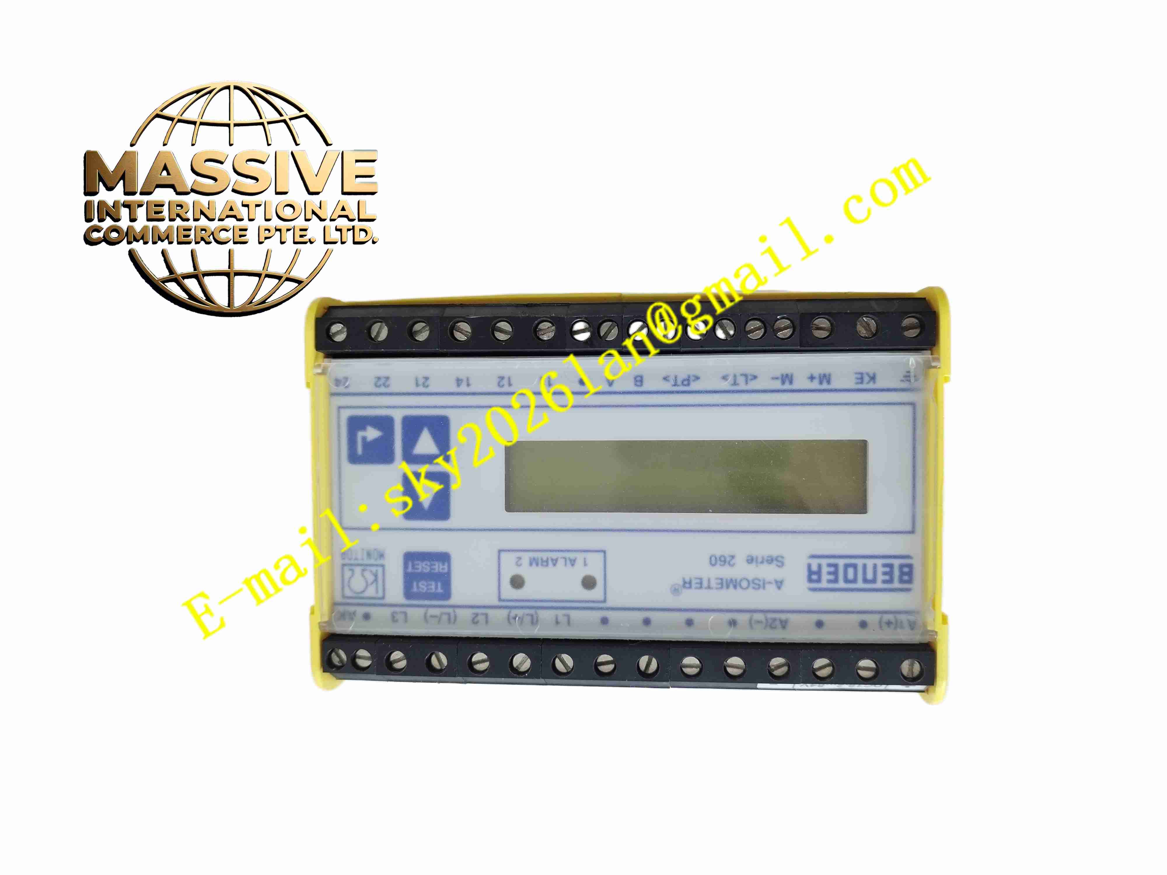
Bender IRDH265-2
Technical Specifications
- Product Type: Insulation monitoring device for IT unearthed power system
- Monitored System: AC, DC and mixed AC/DC IT network
- Measurement Range: Wide insulation resistance measurement range
- Measuring Voltage: Low superimposed measuring voltage to avoid system disturbance
- Response Threshold: Adjustable insulation resistance alarm setpoint
- Power Supply: Wide range auxiliary power supply
- Output Contacts: Two potential free relay alarm contacts
- Mounting: 35 mm DIN rail mounting
- Ingress Protection: IP20 for cabinet installation
- Operating Temperature: -20 °C to +70 °C
- Humidity: 10 % to 95 %, non-condensing
- Certifications: IEC 61557, CE, UL, marine classification approvals
- Weight: 0.48 kg
Functional Features
- Continuous real-time measurement of insulation resistance between power conductors and protective earth in IT systems.
- Adjustable alarm threshold for insulation resistance, two stage alarm function available.
- Potential free relay contacts output alarm signal to PLC, SCADA and local alarm panel.
- Detect DC offset voltage in mixed AC/DC power systems.
- Built-in fault memory retains alarm records until manual reset.
- Front panel digital display shows real-time insulation resistance value and fault code.
- LED indicators display power status, normal operation and alarm state.
- Manual test button verifies device function and alarm loop on site.
- Suppress interference caused by system leakage capacitance in inverter driven power networks.
- Continuous self-monitoring checks internal circuit health of the insulation monitor.
Application Scenarios
- Shipboard unearthed IT power distribution system
- Hospital medical isolated power supply network
- Mining underground IT power distribution
- Industrial uninterruptible IT power system
- Offshore platform electrical safety monitoring
Material Composition
- Housing: Flame retardant polycarbonate plastic DIN rail enclosure
- Main PCB: FR4 printed circuit board
- Measurement circuit: Precision measuring resistors and signal processing microcontroller
- Relay: Electromagnetic relay for alarm contact output
- Display: Digital segment LCD screen
- Terminal block: Tin plated copper alloy screw terminals for power and system wiring
Structural Characteristics
- Slim rectangular DIN rail plastic housing.
- Front panel integrates LCD display, LED indicators and manual test button.
- Top and bottom screw terminal blocks for power supply and system connection.
- Internal measurement circuit isolates superimposed measuring signal from main power circuit.
- Passive convection cooling design without fan.
Working Principle IRDH265-2 superimposes low amplitude measuring signal between the unearthed IT power system and protective earth. The measuring circuit detects the leakage current flowing through insulation resistance. The microcontroller calculates insulation resistance value based on measured leakage current. When insulation resistance drops below the first alarm threshold, the first relay activates. When insulation continues to degrade to second threshold, the second alarm relay triggers. The front panel displays resistance value and alarm code. The manual test button injects simulated insulation fault signal to verify complete monitoring and alarm chain.
Installation Requirements
- Mount IRDH265-2 on standard 35 mm DIN rail inside electrical cabinet.
- Connect device auxiliary power supply and measuring terminals to IT power system.
- Connect relay alarm contacts to plant alarm or PLC digital input circuit.
- Set insulation alarm threshold according to local electrical safety specification.
- Execute manual test after wiring to verify alarm output function.
- Configure fault reset mode as manual or automatic according to system requirement.
Usage Notes
- This device only applies to unearthed IT power systems, cannot be used in earthed TN or TT power systems.
- Do not connect overvoltage to measuring terminals.
- Keep cabinet dry and free of conductive dust.
- Perform regular manual function test as part of electrical maintenance schedule.
- Disconnect auxiliary power before modifying wiring.
- Replace unit immediately when permanent measurement circuit or display fault occurs.