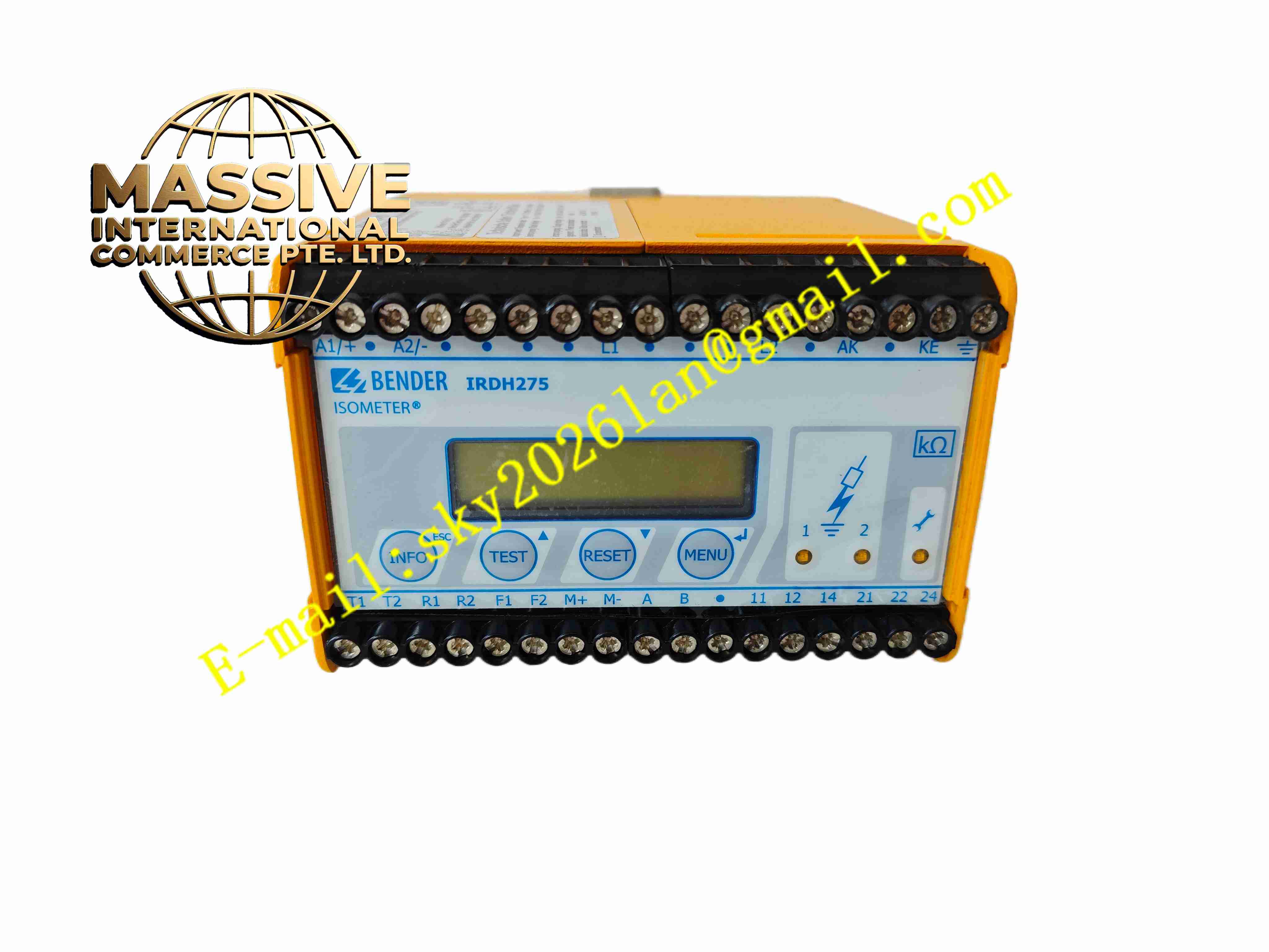
Description
Bender IRDH275-435
Technical Specifications Monitoring voltage range AC/DC 0…435V; Adjustable response threshold 1kΩ to 10MΩ; Supply voltage DC24V; Two independent alarm relay outputs; 4…20mA analog measurement output; RS485 BMS bus communication; DIN rail mounting; Protection class IP20.
Functional Features Continuous real-time insulation resistance measurement; Automatic adaptive compensation for system stray capacitance; Built-in comprehensive self-test circuit with internal test button; Two configurable alarm relays with selectable normally open or normally closed contacts; Historical fault value storage with timestamp; BMS bus for networked monitoring and parameter configuration; Analog output transmits real insulation resistance value to PLC or SCADA; System hardware fault alarm function.
Application Scenarios Hospital isolated medical power supply systems; Mining underground IT power distribution; Marine vessel isolated power grids; Industrial UPS and emergency power supply systems; Chemical explosion-proof non-grounded power networks.
Performance Parameters Operating ambient temperature -20℃ to +60℃; Storage temperature -40℃ to +85℃; Relative humidity 5% to 95%, no condensation; Insulation test voltage 2.5kV AC; Compliance with IEC61557-8, EN61557-8 standards.
Material Composition Flame-retardant ABS plastic housing; Multi-layer glass fiber PCB board; Precision measuring resistors; Isolation signal transformers; Electromechanical alarm relays; LED status indicators; Brass nickel-plated screw terminals.
Structural Characteristics Compact rectangular DIN rail housing; Front panel with adjustment knobs and status LED indicators; Upper and lower terminal blocks for power supply, measured network and signal wiring; Internal physical separation between measuring circuit and power circuit.
Working Principle The device injects low-amplitude measuring signal into the unearthed IT power network. The sampling circuit captures leakage current generated by insulation defects. The microcontroller calculates insulation resistance according to measured voltage and current. When resistance drops below preset threshold, the alarm relay activates and triggers alarm output. The built-in self-test circuit verifies measurement channel integrity periodically.
Installation Requirements Mount on standard DIN rail inside electrical cabinet. Separate measuring cables from high-power cables and use shielded twisted pair. Complete protective earthing of cabinet housing. Set alarm threshold according to system design before power-on. Execute manual self-test to verify alarm function.
Usage Notes Cut off power supply before wiring or disassembly. Do not replace internal measuring components with non-original spare parts. Keep the device away from strong electromagnetic interference sources. Conduct periodic calibration according to electrical safety regulations. Avoid operation in environment with conductive dust.