Description
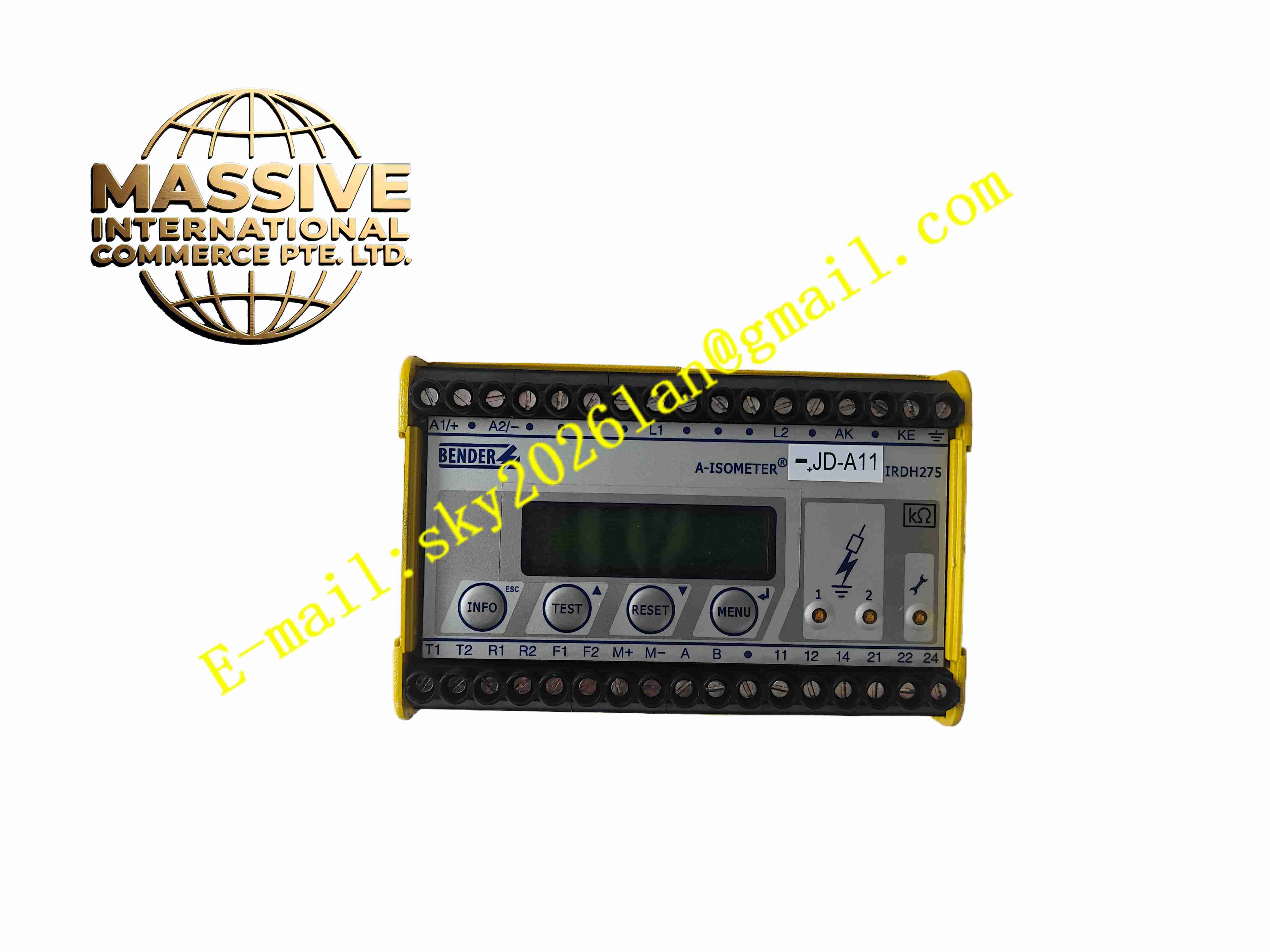
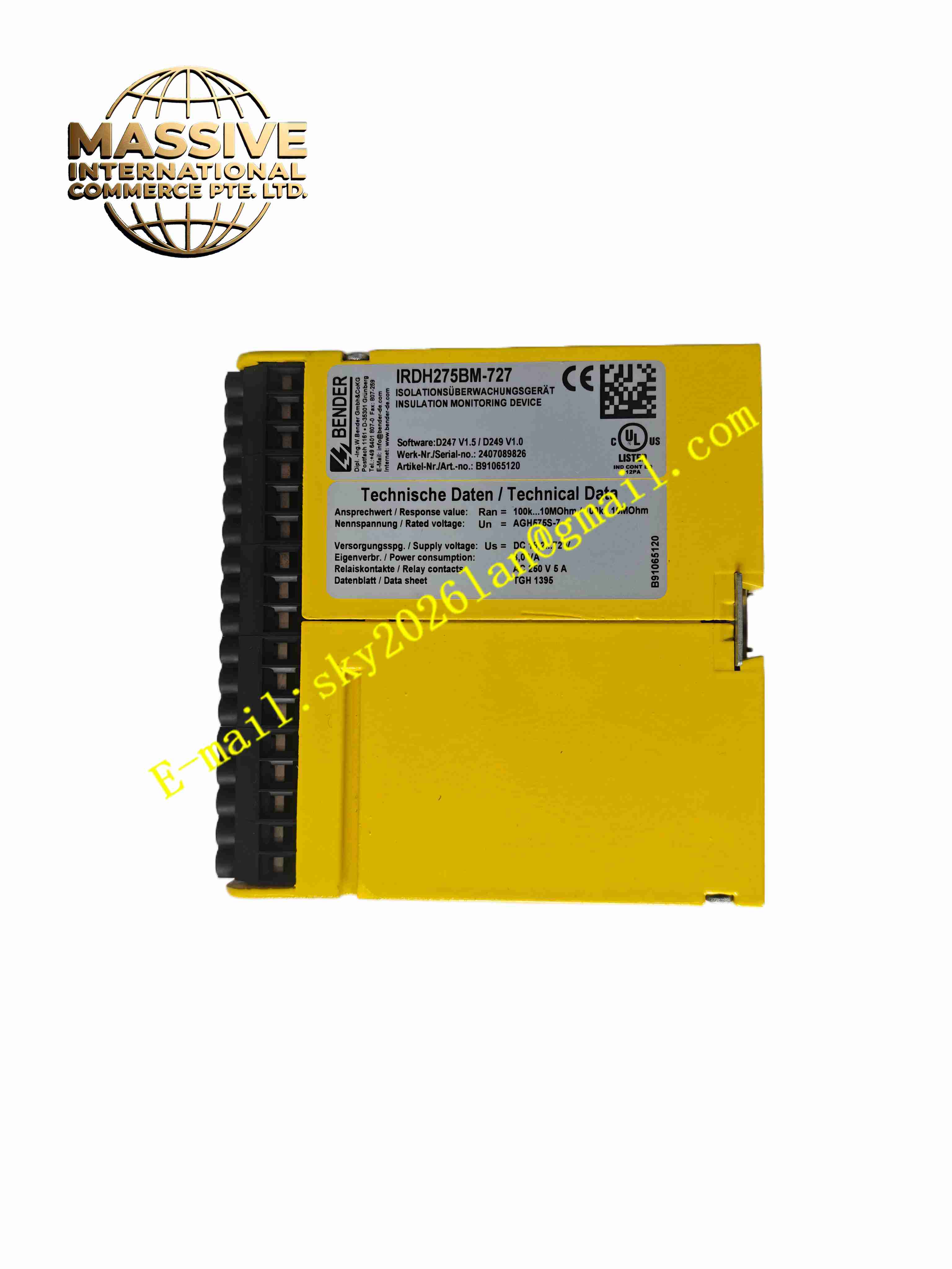
Bender IRDH275BM-727
Technical Specifications
- Monitoring object: Unearthed IT system ground insulation
- Measuring range: 1 kΩ to 10 MΩ
- System voltage: AC 0 to 793 V / DC 0 to 893 V
- Alarm output: Multi-stage relay contacts
- Communication: RS485 / bus extension
- Relay contact rating: AC250 V 5 A / DC30 V 5 A
- Supply: AC115 to 230 V
- Display: LCD
- Temperature: -20 °C to +55 °C
- Storage: -30 °C to +70 °C
- Humidity: 5 % to 95 %, non-condensing
- Protection: IP40
- Installation: DIN rail
- Extension: Bender bus for remote display
Functional Features
- Continuous monitoring of unearthed system ground insulation
- Multi-stage alarm threshold relay output
- LCD display of insulation resistance
- Active test signal injection measurement
- RS485 bus to upper monitoring system
- Parallel networking of multiple monitors for multiple systems
- Extension interface to Bender remote display units
- Front panel LEDs and push buttons
- Adapts to AC/DC mixed systems
- DIN rail compact design
Application Scenarios
- Hospital IT centralized insulation monitoring networking
- Industrial plant unearthed distribution insulation monitoring
- Photovoltaic plant DC side insulation monitoring
- Rail transit traction power insulation monitoring
- Data center UPS insulation monitoring
- Marine power system insulation monitoring
Materials and Construction
- Housing: Flame-retardant engineering plastic
- Front panel: LCD and push buttons
- PCB: FR4 board
- Core: Test signal generator and measurement circuit
- Relay: Industrial electromagnetic relay
- Communication: RS485 isolated transceiver
- Terminals: Screw-fastened terminals
Structural Features
- Narrow DIN rail plastic housing
- Front panel LCD, push buttons, status LEDs
- Side terminals for supply, relays, and communication
- Internal circuit partitions
- Extension connector to remote display
- Fanless natural convection
Working Principle The instrument connects to the unearthed system via L+ and L-; the internal test signal generator injects a low-frequency test voltage to ground. The measurement circuit computes ground insulation resistance from test current. The LCD displays resistance; below threshold the corresponding relay operates. RS485 uploads insulation data to the upper system. Multiple units network via the Bender bus; remote displays centrally show each system’s insulation state.
Installation Requirements
- Snap-mount on 35 mm DIN rail
- Connect L+ and L- of monitored system
- Use shielded twisted pair for RS485, terminate both ends with 120 Ω
- Connect AC115 to 230 V supply
- Reliably ground PE
- Cabinet temperature -20 °C to +55 °C
- Set unique bus address when networking multiple units
Precautions
- Monitored system must be unearthed IT
- Set unique station address when networking
- Terminate RS485 bus ends
- Set alarm thresholds per system requirements
- Periodically push button to test alarm function
- Store spares in dry environment