Description
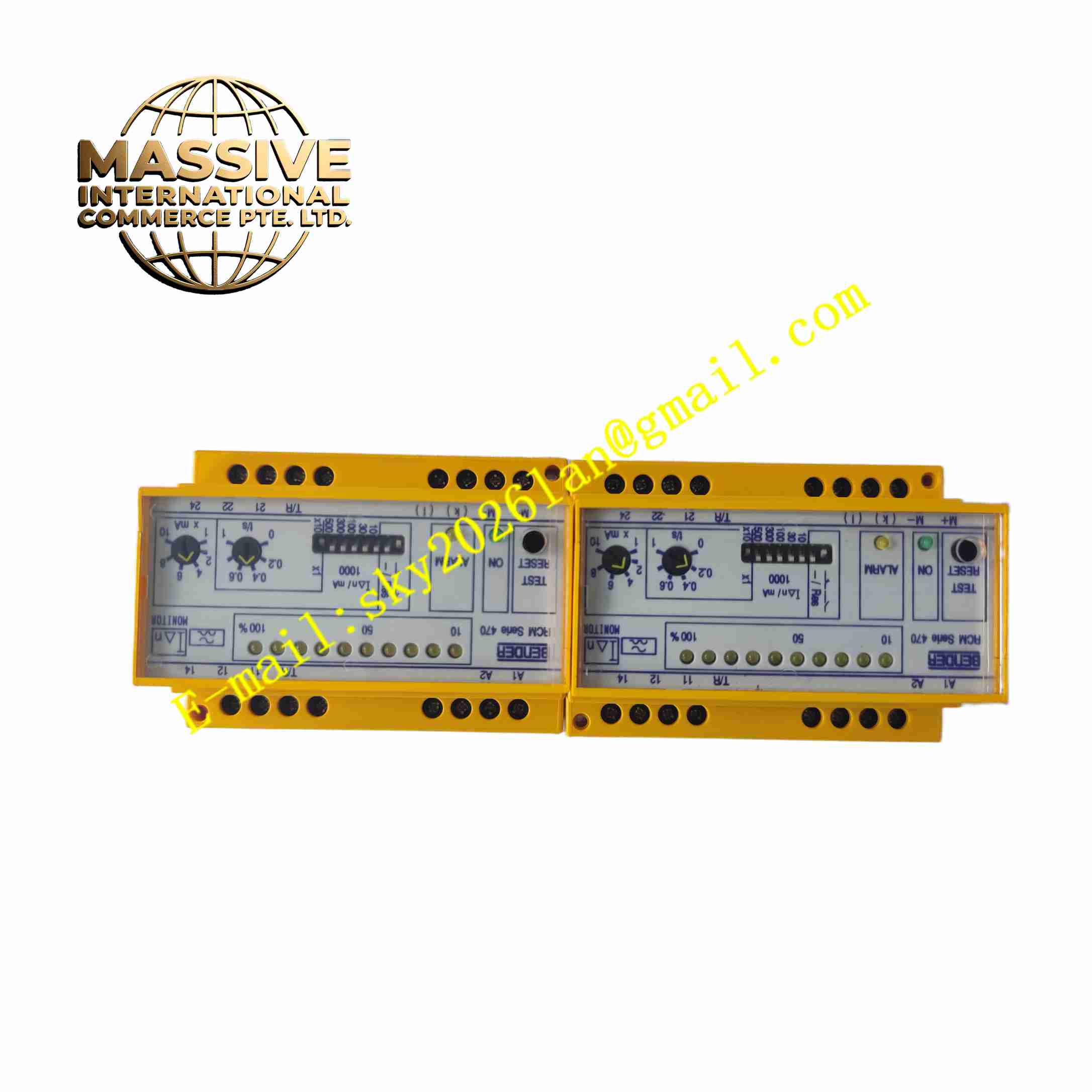
BENDER RCM475LY-13 Residual Current Monitor
Technical Specifications Model: RCM475LY-13 Brand: Bender Measured Current Type: AC, DC and pulsating DC residual current Power Supply: Auxiliary DC or AC power supply Measurement Range: Adjustable residual current measuring range Output: Potential-free relay alarm contact Communication: Optional bus interface for system integration Operating Temperature: -20 ℃ ~ +60 ℃ Storage Temperature: -40 ℃ ~ +85 ℃ Relative Humidity: 10% ~ 95%, non-condensing Mounting: DIN rail mounting Protection Class: IP20
Functional Features Continuously monitors residual leakage current in AC/DC mixed low voltage systems. Two-stage adjustable alarm thresholds for pre-alarm and main alarm. Potential-free relay contact outputs alarm signal to PLC or alarm panel. Built-in self-test function verifies measurement circuit integrity regularly. LED indicators display measured value, pre-alarm status and fault alarm status. Delay function prevents false alarm caused by transient residual current peak. Supports connection with external current transformer for residual current sampling. Records fault occurrence time and residual current value when alarm triggers.
Application Scenarios Industrial low-voltage power distribution cabinet, battery energy storage system, medical power supply network, photovoltaic power generation system, data center power monitoring, marine low voltage electrical system, charging station power loop monitoring.
Performance Parameters Maintains accurate residual current measurement under wide temperature fluctuation. Self-test circuit verifies hardware function automatically at regular intervals. Relay contact outputs stable alarm signal once leakage current exceeds threshold. Delay circuit suppresses transient current spike and avoids false triggering. Measurement function keeps stable under industrial electromagnetic interference. Internal memory stores alarm records for later maintenance check.
Material Composition Housing: Flame-retardant PA plastic DIN rail module housing. Main PCB: FR4 printed circuit board with conformal coating. Core Electronic Components: Current signal sampling chip, microprocessor, relay, EMC protection components, reference voltage chip, non-volatile memory. Terminal Parts: Copper alloy screw terminals. Indicator Components: LED indicators for power, pre-alarm and main alarm. Fasteners: Metal spring clip for DIN rail fixing.
Structural Features Compact rectangular plastic housing designed for NS35 standard DIN rail installation. Front panel carries LED indicators, test button and threshold setting elements. Metal spring clip fixed on module backside locks the unit onto DIN rail. Front screw terminals for auxiliary power supply, relay output and signal wiring. Internal isolation barrier separates power circuit and measurement signal circuit. Housing prevents direct human contact with live terminals after installation.
Working Principle Auxiliary power supplies the residual current monitor. The residual current transformer samples vector sum of all phase conductors and neutral conductor current in monitored power loop. The sampled current signal enters RCM475LY-13 internal measurement circuit. The microprocessor calculates residual current value and compares measured value with preset threshold. When residual current reaches pre-alarm threshold, pre-alarm LED activates. When residual current rises to main alarm threshold, main alarm LED lights up and relay contact switches state to send alarm signal to upper control system. The built-in self-test circuit injects test signal periodically to check measurement circuit function. All alarm events are stored in internal memory.
Installation Requirements Mount the device on NS35 DIN rail inside closed electrical cabinet. Connect auxiliary power supply to designated power terminals. Wire residual current transformer secondary side to signal input terminals. Connect relay alarm contact wiring to PLC or central alarm panel. Set residual current alarm threshold through front panel adjustment. Carry out self-test operation after wiring completion to verify function. Keep the module away from large current power cables to reduce interference.
Usage Precautions Module protection grade is IP20, install only inside closed electrical cabinet. Do not exceed rated voltage of auxiliary power supply. Check current transformer wiring polarity strictly according to manual. Perform regular self-test to confirm monitoring function availability. Check terminal screw tightness during periodic maintenance. Do not modify internal circuit, modification invalidates product warranty. Cut off auxiliary power before changing threshold or rewiring.