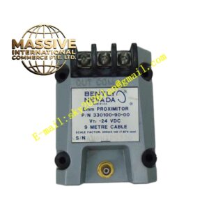
Description
Bently 130118‑0025‑02
Technical Specifications:
- Physical Length: 2.5 meters
- Compatible Sensor: 3300 NSv series proximity probe
- Connector Style: Bently NSv dedicated miniature coaxial connectors at both ends
- Cable Insulation Material: FEP fluoropolymer
- Shielding Structure: Double‑layer copper‑braid full coverage shielding
- Operating Temperature Range: ‑55 °C ~ +175 °C
- Storage Temperature: ‑60 °C ~ +180 °C
- Minimum Bending Radius: 12 times cable outer diameter
- Insulation Resistance: ≥1000 MΩ
- Characteristic Impedance: Strictly controlled factory‑calibrated impedance for NSv transducer system
- Weight: 0.18 kg Functional Features:
- Factory‑controlled precise electrical‑length parameter; every cable undergoes factory impedance and electrical‑length calibration test before delivery.
- Double‑layer full‑coverage shielding structure suppresses external electromagnetic noise interference onto low‑level eddy‑current‑sensor high‑frequency signals.
- FEP fluoropolymer insulation material delivers outstanding oil‑resistance, solvent‑resistance, high‑temperature‑aging‑resistance performance for turbine‑compressor field environment.
- Dedicated NSv miniature coaxial connectors guarantee low‑impedance stable connection, reduce signal‑reflection risk.
- Supports combination‑matching with NSv probe to constitute total 5‑meter or 7‑meter complete NSv transducer‑system for 990 / 991 transmitters.
- Compact cable outer diameter adapts for narrow‑space wiring inside equipment enclosures and cable‑tray routing. Application Scenarios: Radial‑vibration and thrust‑position NSv proximity‑probe signal extension; compressor, pump and turbine machinery‑monitoring field‑signal wiring; cabinet‑to‑field‑probe signal‑cable segments for NSv transducer systems; machinery‑retrofit monitoring‑point reconstruction projects. Performance Parameters: Low high‑frequency signal attenuation; consistent impedance along full cable length; excellent long‑term thermal‑cycle stability; low capacitance tolerance within factory‑specified limit. Material Composition: FEP fluoropolymer inner insulation layer; central solid copper signal conductor; inner copper‑braid shielding layer; outer copper‑braid shielding layer; FEP outer jacket; nickel‑plated brass NSv coaxial connectors; high‑temperature sealing gaskets inside connector assembly. Structural Characteristics: Flexible round coaxial‑cable construction; dedicated NSv miniature coaxial male‑female connectors assembled and potted at both cable ends; cable outer surface printed with full part number, length marking and production serial‑number identification. Working Principle: Transmits high‑frequency excitation signal from 990 / 991 integrated‑transmitter to NSv probe coil; transmits impedance‑variation induced high‑frequency return‑signal from probe back to transmitter circuit. Strictly controlled electrical‑length and impedance avoid signal reflection and phase‑shift deviation which would degrade measurement linearity and accuracy. This extension‑cable itself does not implement signal‑processing function; it acts as calibrated signal‑transmission medium for NSv proximity‑transducer loop. Installation Requirements:
- Maintain minimum bending radius 12 times cable outer‑diameter; sharp dead‑bending permanently damages internal shielding and conductor structure.
- Route NSv extension‑cable separately away from high‑power motor cables, variable‑frequency‑drive power‑cables and high‑current power‑wiring. Maintain adequate separation distance to avoid electromagnetic‑noise coupling.
- Tighten both‑end coaxial connectors by hand torque; never use metal pliers wrench to turn cable jacket, only turn connector knurled nut.
- Avoid heavy squeezing, crushing and sharp‑edge abrasion to cable body during installation and cable‑tray laying.
- Calculate total complete‑system electrical‑length: sum NSv probe inherent electrical‑length plus this extension‑cable electrical‑length, total must match transmitter factory‑calibrated system‑length setting. Usage Notes:
- Do not cut, splice or re‑solder this factory‑calibrated extension‑cable. Any cutting or splicing changes electrical‑length and impedance parameters, invalidates factory calibration and produces large‑measurement‑error.
- Keep connectors dry and clean; prevent oil, water and process‑medium intrusion into connector interior cavity.
- Do not perform high‑voltage megger insulation test across NSv cable conductors; high‑voltage destroys FEP insulation and internal connector assembly.
- Inspect connector tightening status and cable outer‑jacket integrity during each unit overhaul cycle.
- Mixed‑use of non‑NSv‑series general coaxial‑cable as replacement extension‑cable is strictly prohibited.